
531X307LTBAJG1 | GE LAN I/O Terminal Card for EX2000
Introduction:
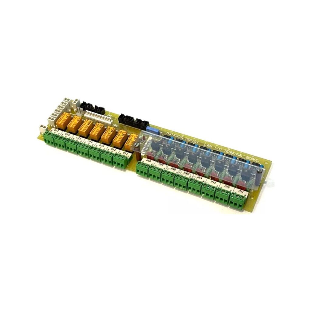
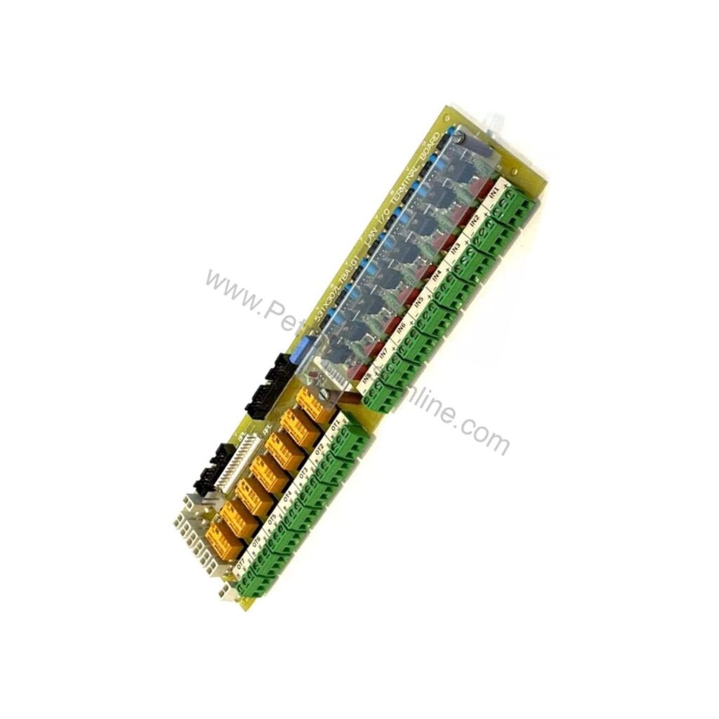
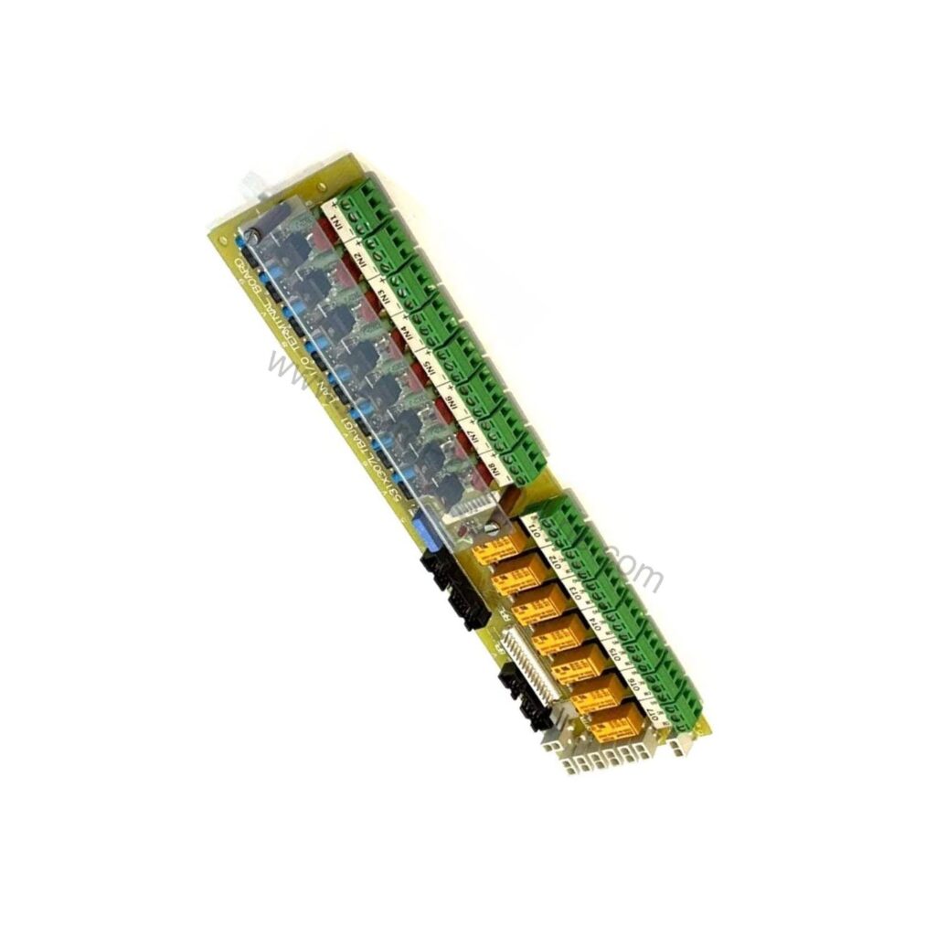
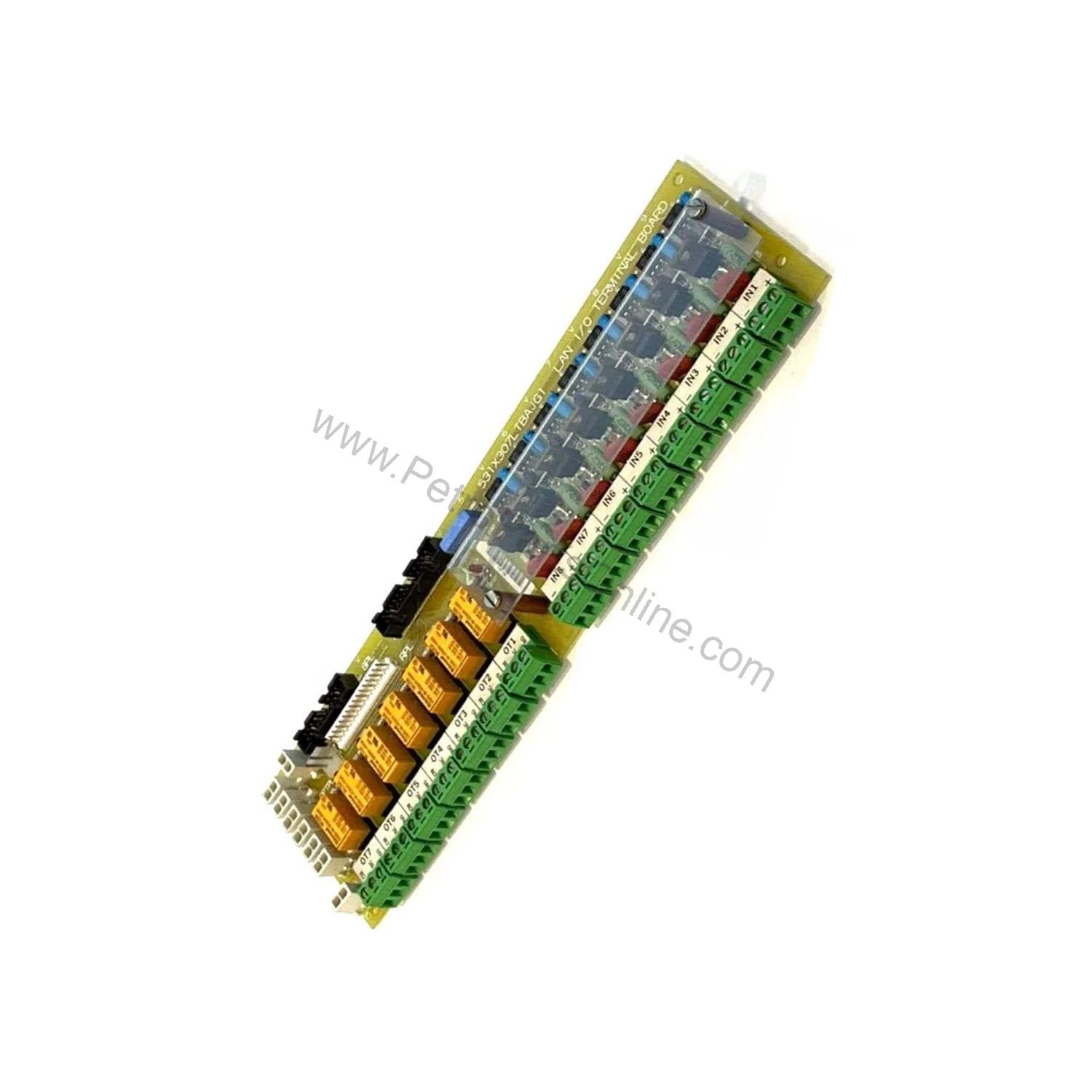
GE 531X307LTBAJG1 LAN I/O Terminal Card for EX2000 drives: 8 configurable 24 V dc inputs, 7 form C relay outputs, and 15 LED indicators for field diagnostics.
 Customer Reviews
UBEST Automation – Trusted Global Automation Parts Supplier
We offer a wide range of in-stock industrial automation spare parts. All products come with a 12-month warranty and a 30-day refund for quality issues.
Product Attributes:
Notice: For real-time prices and inventory, please click the button below to contact us.
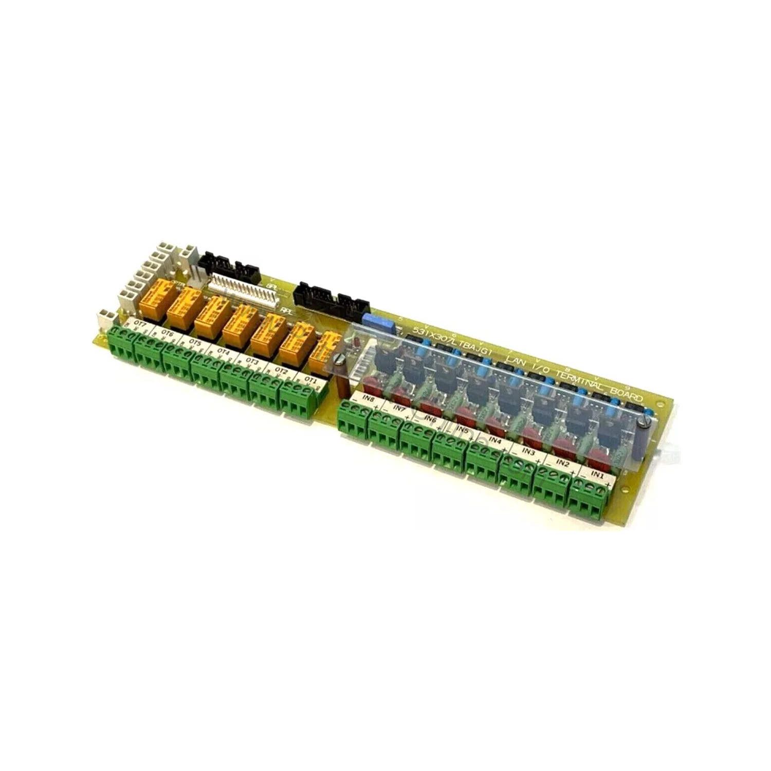
GE 531X307LTBAJG1 is a LAN I/O Terminal Card for the EX2000 series, manufactured in the USA by General Electric. It provides eight 24 V dc configurable control input plugs and seven form C relay contact outputs, with 15 LED indicators for at-a-glance status monitoring. The card is housed in the drive or exciter cabinet and has no adjustable hardware, so setup is fixed at the factory.
What does this unit do in an EX2000 drive cabinet?
The LAN Terminal Board (LTB) links control devices such as drives with external devices including contactors, indicator lights, pushbuttons, and interlocks. It converts field input signals to 24 V dc logic levels for the drive control board. The G1 LTB accepts eight input terminal sets for 24–240 V ac or dc signals, and its eight CI1PL–CI8PL plugs are 24 V dc programmable control inputs. These inputs connect to the 8PL bus, which carries I/O signals between the LTB, the NTB/3TB terminal board, and the drive control board. Because the board has no adjustable hardware, maintenance focuses on wiring integrity and LED status rather than calibration.
Key features and technical specifications
- Inputs: Eight configurable 24 V dc control input plugs (CI1PL–CI8PL) on the G1 LTB.
- Input voltage range: Eight input terminal sets accept 24–240 V ac or dc field signals.
- Outputs: Seven low-voltage, low-current form C relay contact connectors (OT1–OT7), each with three terminals.
- Relay drive: Seven high-voltage, high-current relays are activated by pilot contact connections.
- Indicators: 15 LEDs — LED1–LED8 show source applied to IN1–IN8; LED17–LED23 show relays RX1–RX7 energized.
- Switching thresholds: Turn-on and turn-off thresholds are 6 V, 0.5 mA peak ac/dc.
- Connector types: Plug-in connectors (PL) for ribbon cables and terminal board connectors (TB) for individual wires.
- Series: EX2000; country of manufacture: United States (USA).
The combination of per-channel LEDs and fixed thresholds makes the card easy to troubleshoot in the field: a technician can confirm input presence and relay state without a meter. For any specification not listed here, refer to the official GE datasheet.
Frequently Asked Questions
What input voltage does the 531X307LTBAJG1 accept?
The GE 531X307LTBAJG1 has eight input terminal sets for 24–240 V ac or dc signals, which are converted to 24 V dc logic for the drive control board. The G1 version also provides eight 24 V dc configurable control input plugs (CI1PL–CI8PL).
How many relay outputs does this card provide?
It provides seven low-voltage, low-current form C relay contact connectors (OT1–OT7), each with three terminals. Seven high-voltage, high-current relays are activated by pilot contact connections.
What do the LED indicators show on the 531X307LTBAJG1?
The card includes 15 LEDs: LED1–LED8 turn on when source is applied to circuits IN1–IN8, and LED17–LED23 turn on when relays RX1–RX7 are energized. These indicators support quick field diagnostics.
Is this card suitable for plc module replacement in EX2000 systems?
Yes, the GE 531X307LTBAJG1 is a LAN I/O Terminal Card for the EX2000 series. Its G1 configuration includes the 8PL connector and CI1PL–CI8PL plugs, which are absent on the G2 LTB, so confirm your existing wiring before ordering.
What are the ON/OFF thresholds for this LTB?
Turn-on and turn-off thresholds are both 6 V, 0.5 mA peak ac/dc. Devices in series with an input can hold it ON if leakage current exceeds 0.5 mA.
Why choose this LAN I/O Terminal Card for plc module replacement?
When a legacy EX2000 drive needs a replacement I/O interface, this unit is the G1 revision with the full set of eight 24 V dc input plugs and eight ac/dc input terminal sets. The G2 LTB omits the 8PL connector and CI1PL–CI8PL plugs and accepts only dc signals at IN1–IN8. Maintenance teams therefore select the G1 card when the existing wiring uses the plug-in input connectors or ac field signals. The card's 15 LEDs give immediate feedback on channel status, which shortens fault-finding during planned outages. Its fixed ON/OFF thresholds (6 V, 0.5 mA peak ac/dc) also simplify verification because there are no potentiometers to adjust.
Installation and wiring guidance
Mount the LTB in the drive or exciter cabinet and connect field wiring to the terminal board connectors (TB) and ribbon cables to the plug-in connectors (PL). Route I/O ribbon cables separately from power wires to avoid induced noise. In ac applications, capacitive coupling between connection wires can cause input leakage on IN1–IN8, so keep signal leads short and separated from power conductors. Note that devices connected in series with an input can hold it permanently ON if leakage current exceeds 0.5 mA. After wiring, use the LEDs to confirm each input and relay state before returning the drive to service.
Reliability and maintenance in oil and gas service
Because the LTB has no adjustable hardware, routine maintenance centers on visual inspection of terminal connections and LED behavior. During scheduled outages, check for loose terminal screws, damaged ribbon cables, and discolored relay contacts. Confirm that all 15 LEDs respond correctly when inputs are energized and relays are commanded. In harsh oil and gas environments, protect the cabinet from excessive dust and moisture, and verify that enclosure seals remain intact. The card's fixed thresholds eliminate drift concerns, so any change in input behavior usually points to field wiring or an external device rather than the board itself.
Compatibility and integration notes
this unit works with the EX2000 series and connects to the NTB/3TB terminal board and the drive control board through the 8PL bus. Relay contacts from both the LTB and RTBA are accessible when the two boards are used together. When integrating this card into a larger control system, confirm that field devices match the input voltage range (24–240 V ac or dc) and that output loads are within the form C relay ratings. If the application requires a network gateway or protocol converter, verify compatibility with the supplier before installation.
Frequently asked questions
What input voltage does this unit accept?
The GE this unit has eight input terminal sets for 24–240 V ac or dc signals, which are converted to 24 V dc logic for the drive control board. The G1 version also provides eight 24 V dc configurable control input plugs (CI1PL–CI8PL).
How many relay outputs does this card provide?
It provides seven low-voltage, low-current form C relay contact connectors (OT1–OT7), each with three terminals. Seven high-voltage, high-current relays are activated by pilot contact connections.
What do the LED indicators show on this unit?
The card includes 15 LEDs: LED1–LED8 turn on when source is applied to circuits IN1–IN8, and LED17–LED23 turn on when relays RX1–RX7 are energized. These indicators support quick field diagnostics.
Is this card suitable for plc module replacement in EX2000 systems?
Yes, the GE this unit is a LAN I/O Terminal Card for the EX2000 series. Its G1 configuration includes the 8PL connector and CI1PL–CI8PL plugs, which are absent on the G2 LTB, so confirm your existing wiring before ordering.
What are the ON/OFF thresholds for this LTB?
Turn-on and turn-off thresholds are both 6 V, 0.5 mA peak ac/dc. Devices in series with an input can hold it ON if leakage current exceeds 0.5 mA.
Contact PetroPartsOnline for parts suited to your application's requirements.