
IS215VPROH2BC | GE 125 VDC Turbine Protection Board
Introduction:
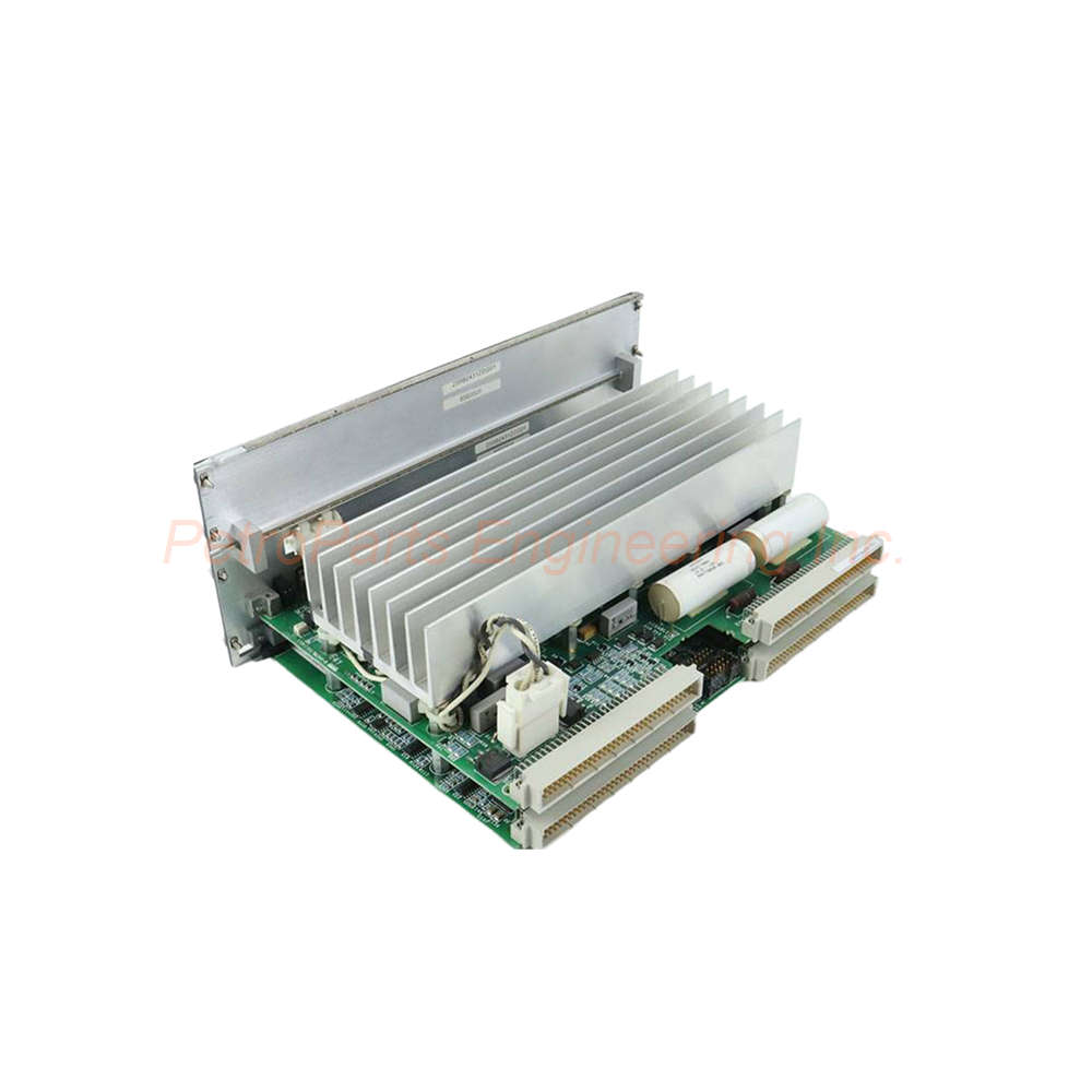
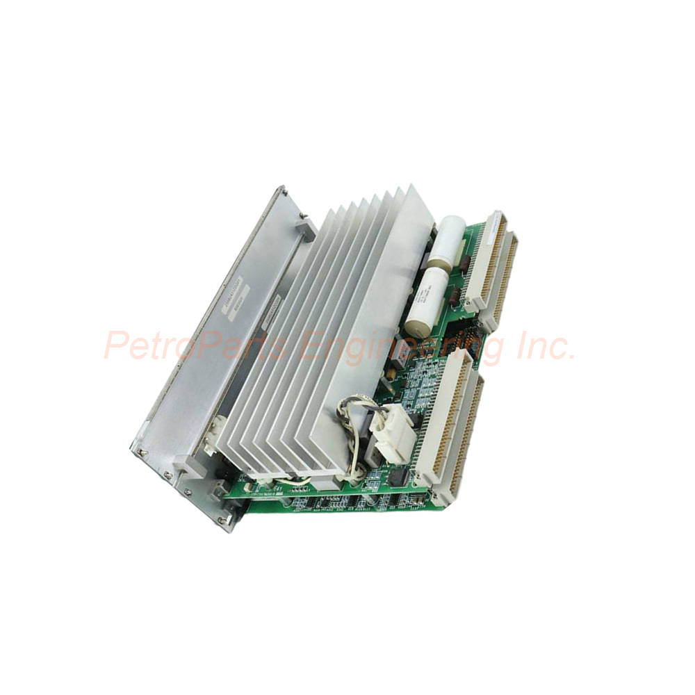
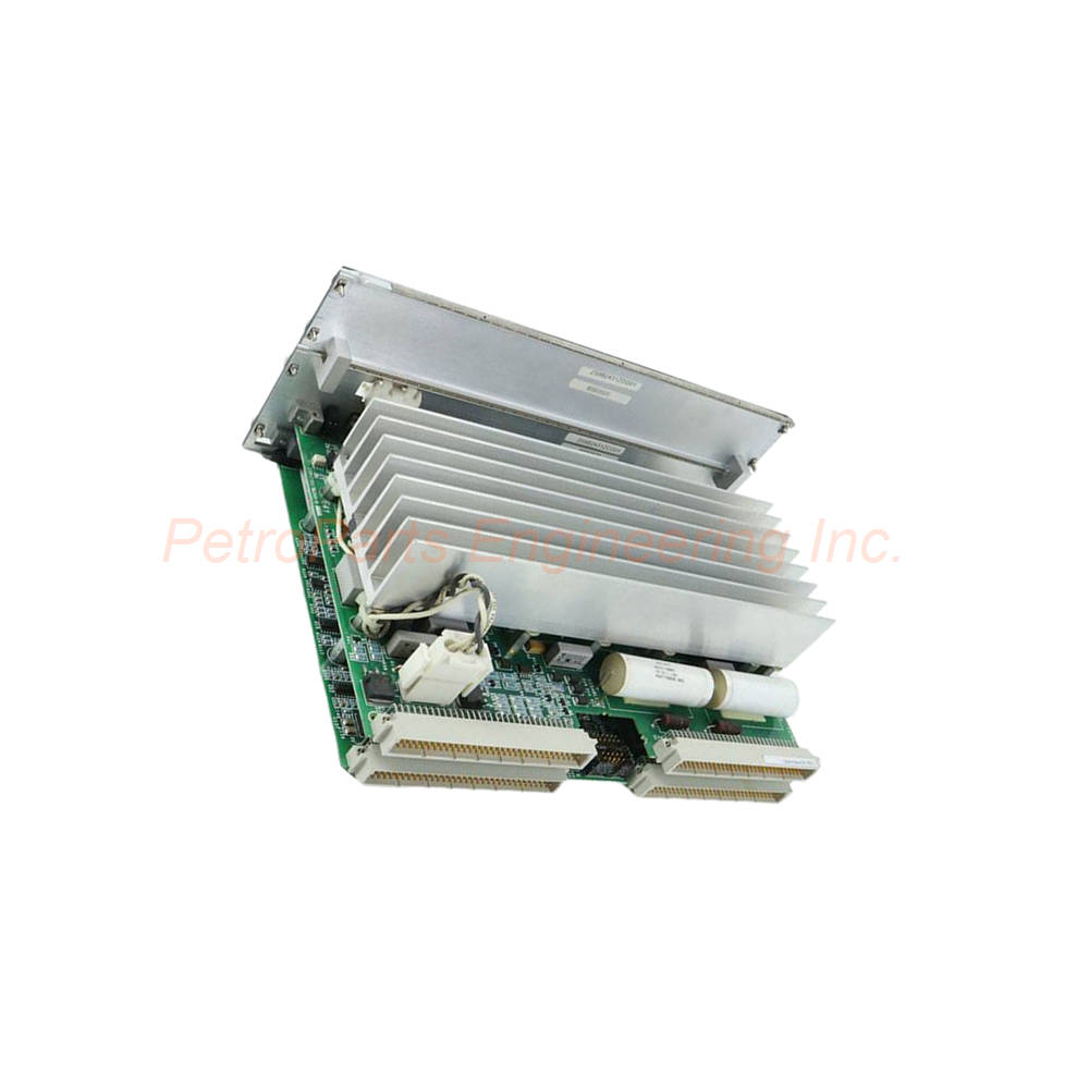
The IS215VPROH2BC is a GE Mark VI turbine protection board with a 125 VDC power supply, 0 to 60 °C operating range, and MPU input sensitivity from 2 Hz to 20 kHz.
 Customer Reviews
UBEST Automation – Trusted Global Automation Parts Supplier
We offer a wide range of in-stock industrial automation spare parts. All products come with a 12-month warranty and a 30-day refund for quality issues.
Product Attributes:
Notice: For real-time prices and inventory, please click the button below to contact us.
What the IS215VPROH2BC Delivers in Turbine Protection
The GE this unit is a turbine protection board from the Mark VI series. It operates as an emergency trip and protection processor with a 125 VDC power supply rating and an operating temperature range of 0 to 60 °C. The board is built for demanding environments where overspeed protection must remain available during critical operation.
This module serves as the input/output processor for the TPRO and TREG terminal boards. In a protection application, it works with the TPRO board to guard against turbine overspeed. When interfacing with the emergency trip board, it pairs with the TREG board. The architecture places triple redundant VPRO boards in a dedicated Protection Module, separate from the turbine control system.
Key Specifications of this unit Turbine Protection Board
- Part Number: this unit
- Manufacturer: General Electric
- Product Type: Turbine Protection Board
- Series: Mark VI
- Power Supply Rating: 125 VDC
- Operating Temperature: 0 to 60 °C
- Frame Rate: Up to 100 Hz
- MPU Pulse Rate Range: 2 Hz to 20 kHz
- MPU Pulse Rate Accuracy: percent of reading
- Country of Manufacture: United States of America (USA)
- Availability: In Stock
The 125 VDC input is drawn from the cabinet Power Distribution Module (PDM). Each board carries its own on-board power supply that generates 5 VDC and 28 VDC for internal components. Because every VPRO board has an independent supply, the protection module contains three separate power sources. This redundancy limits the impact of a single supply failure on mission-critical trip functions.
Frequently Asked Questions
What power supply does the IS215VPROH2BC require?
The GE IS215VPROH2BC draws 125 VDC from the cabinet Power Distribution Module and generates 5 VDC and 28 VDC through its on-board supply.
What is the operating temperature range of the IS215VPROH2BC?
The GE IS215VPROH2BC is rated for an operating temperature range of 0 to 60 °C.
How many trip solenoids can the IS215VPROH2BC support?
The GE IS215VPROH2BC supports six trip solenoids per VPRO board, with three per TREG board, and a solenoid L/R time constant of 0.1 seconds.
Is the IS215VPROH2BC always triple redundant?
Yes, the GE IS215VPROH2BC is always triple redundant with three independent sections named X, Y, and Z, and one section can be shut down while the turbine runs.
What MPU pulse rate range does the IS215VPROH2BC accept?
The GE IS215VPROH2BC accepts an MPU pulse rate range of 2 Hz to 20 kHz with accuracy stated as percent of reading.
How Redundancy and Trip Circuits Support Reliable Shutdowns
this unit is always triple redundant, with three independent sections designated X, Y, and Z. One section can be shut down while the turbine is running without compromising the protection system. This design supports maintenance and diagnostics without forcing an outage.
Trip solenoid response time is governed by a solenoid L/R time constant of 0.1 seconds. Up to six trip solenoids are supported per VPRO board, with three per TREG board. The TREG terminal board provides the positive side of the 125 VDC power to the solenoids, while the TRPG terminal board supplies the negative side. This dual-sided arrangement adds resilience to the trip solenoid control path.
On the TREG board, 12 relays are controlled by the VPRO. Nine of these relays form three groups of three and implement a voting mechanism for the inputs that control the three trip solenoids. The voting logic reinforces dependable operation in demanding environments.
Integration and Communications
The board includes an Ethernet connection for IONet communications with the control modules. When this unit operates as a turbine emergency trip processor board, it can also connect to the TPRO terminal board through an Ethernet cable. In simplex systems, a third cable extends from J1 to the TSVO terminal board to carry a trip signal and enable a servo valve clamp upon turbine trip.
The only connections between TREG and the control modules are the J2 power cable and the trip solenoids. This simplified connection scheme reduces wiring complexity in the cabinet.
Comparison with Related Protection and Trip Boards
Engineers evaluating this unit often compare it with the parent IS215VPROH2 board and with terminal boards in the same protection chain. The bullet list below highlights the practical differences.
- this unit: Carries B-rated primary and C-rated secondary functional revisions; supports both emergency trip and protection roles.
- IS215VPROH2 (parent): Does not include the two-fold revision table found on this model.
- TPRO terminal board: Used with the VPRO in a turbine protection application; connects through an Ethernet cable.
- TREG terminal board: Used when the VPRO interfaces with the turbine emergency trip board; controls 12 relays and provides the positive side of 125 VDC to trip solenoids.
- TRPG terminal board: Supplies the negative side of the 125 VDC power to the trip solenoids.
These distinctions matter during replacement planning because the revision level and terminal board pairing determine how the board integrates with existing cabinet wiring.
Diagnostics and Field Maintenance
Two diagnostic messages are associated with the K25A synch check relay. A driver mismatch indicates that the requested state of the K25A relay driver does not match its actual state, which may point to wiring faults, improper connections, or configuration discrepancies. A coil trouble message relates to cabling between the TREx and TTUR terminal boards, including an open circuit or a missing P28 V power source on the TTUR board.
Routine inspection should focus on cabinet temperature, since the board is rated for 0 to 60 °C. Verify that the PDM supply remains stable at 125 VDC and that Ethernet and J2 connections are secure. Follow the manufacturer's safety manual for all maintenance activities. For parts suited to your application's requirements, contact PetroPartsOnline.