
DS200PCCAG8ACB | GE 6-Channel Power Connect Card
Introduction:
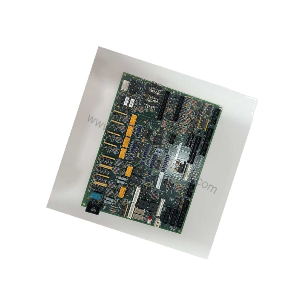
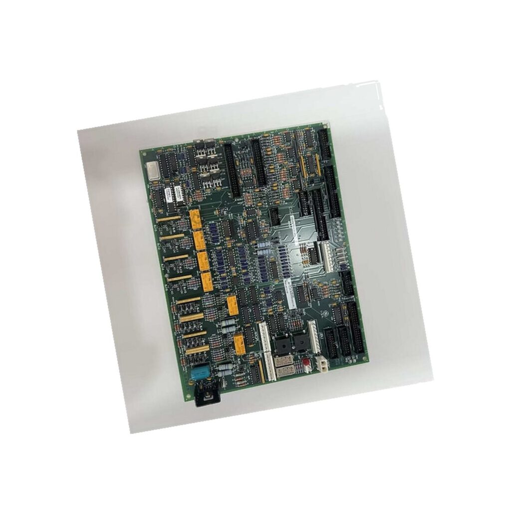
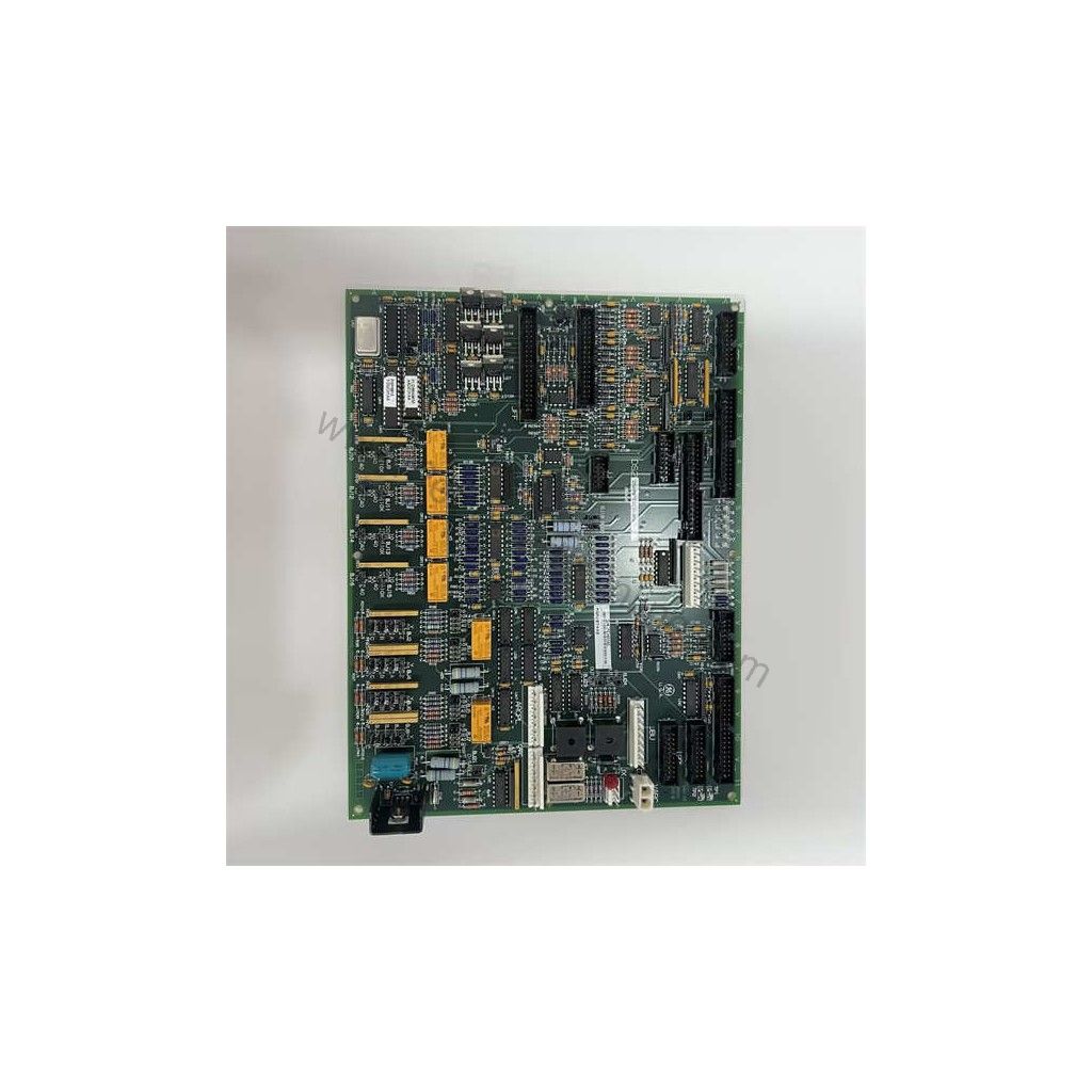
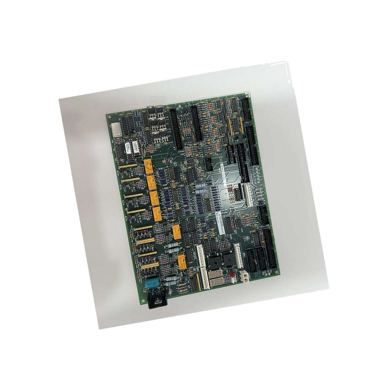
The DS200PCCAG8ACB is a GE PCCA Power Connect Card for EX2000 excitation systems, linking drive control circuitry to the SCR power bridge.
 Customer Reviews
UBEST Automation – Trusted Global Automation Parts Supplier
We offer a wide range of in-stock industrial automation spare parts. All products come with a 12-month warranty and a 30-day refund for quality issues.
Product Attributes:
Notice: For real-time prices and inventory, please click the button below to contact us.
What the DS200PCCAG8ACB Power Connect Card Does
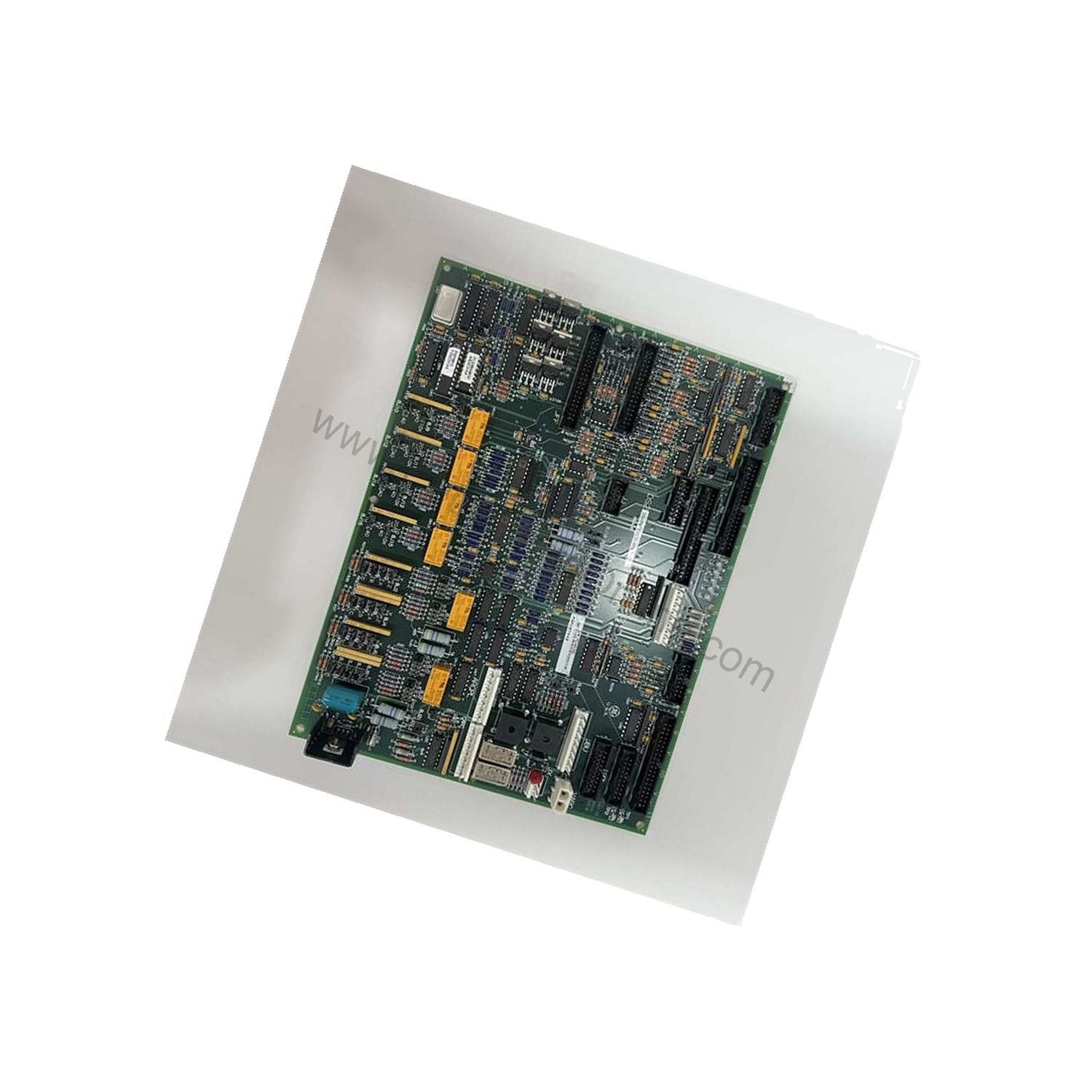
The GE this drive is a PCCA Power Connect Card from the EX2000 Series, used in GE Excitation Control Systems. It acts as the interface between the drive's control circuitry and the SCR power bridge, receiving and transmitting signals to the power supply board, the SCR bridge, and other components in the drive through multiple connectors. The card uses pulse transformers to supply gate drives to the SCR bridge, making it central to drive operation.
For low-to-medium horsepower controllers, the PCCA includes snubber circuits to manage spikes across the AC lines, DC bus, and gate drivers. In higher horsepower controllers, these snubber circuits may be removed from the PCCA and placed elsewhere in the system. The board is built for demanding environments, with an operating temperature range of -30 to 65 °C and surface-mount technology.
Key Specifications of this drive
- Number of channels: 6
- Input span: 1-5 V dc
- Outputs: 24 V dc
- Analog output current: 0-20 mA
- Operating temperature: -30 to 65 °C
- Technology: Surface Mount
- Size: 26.41 cm High x 21.33 cm
- Manual: GEI-100161B
- Country of Origin: United States
These parameters define the card's electrical and environmental envelope. The 1-5 V dc input span and 24 V dc outputs suit the signal levels expected by the drive's control circuitry, while the 0-20 mA analog output current supports current-loop signaling. The wide operating temperature range allows reliable operation in harsh industrial settings.
Solving Signal Integrity Problems in Turbine Drives
One common engineering pain point is signal corruption between the control and the power stage. This drive addresses this by using pulse transformers to supply gate drives, which provides isolation and reliable signal transfer. The board also includes voltage suppression and limitation components such as capacitors, resistors, transistors, and specialized integrated circuits. Several large silver drum-style capacitors or diodes stack across the bottom of the base circuit board, helping to manage voltage spikes.
Another issue is matching the card to the system voltage and configuration. The PCCA board has ten group numbers, and the system voltage, frame size, and whether the system uses regenerative or non-regenerative power conversion determine the group number used. For regenerative systems, groups G1, G7, and G9 cover 240–630 volts; for non-regenerative systems, groups G2, G8, and G10 cover 240–700 volts. Four wire jumpers (JP1, JP2, WP3, and WP4) select system voltage and determine snubber capacitor connections. JP1 and JP2 should be connected to the correct stab terminals (P3 through P10) based on the card group number and system voltage. WP3 and WP4 link stab terminals P2A to P2B and P1A to P1B, respectively, determining whether the snubber capacitors are connected to the same point on the power bridge as the voltage feedback channel.
Installation and Replacement Best Practices
When replacing this drive, it is critical to record where the wires and cables are connected on the defective board. Label the wires and connectors and photograph the board before removal. Cables are fragile; never pull a ribbon cable out from the board by pulling on the ribbon cable. Instead, hold the connector on the board with one hand and the connector on the end of the ribbon cable with the other, then separate them by pulling apart. Unless all signals carried by the ribbon cable are transmitted or received, the drive will not operate correctly, and you may notice operational reliability issues.
If the replacement board is a newer version of the same board, connectors may be rearranged, and components might be different colors or shapes. However, when installed, it will behave the same as the older board because compatibility is verified before you receive it. For parts suited to your application's requirements, contact PetroPartsOnline.
Maintenance and Reliability in Harsh Environments
this drive is built for demanding environments, with an operating temperature range of -30 to 65 °C. To maintain reliability, inspect the board periodically for signs of wear, especially around connectors and capacitors. Ensure the enclosure is free of dust and moisture. The voltage suppression components, including the large drum-style capacitors, should be checked for bulging or leakage. Following the guidelines in manual GEI-100161B helps ensure proper operation. Reliability you can depend on starts with proper handling and installation.
Frequently Asked Questions
What is this drive used for?
The GE this drive is a PCCA Power Connect Card used in GE EX2000 Excitation Control Systems. It interfaces between the drive's control circuitry and the SCR power bridge, supplying gate drives via pulse transformers.
What are the input and output specifications of this drive?
The GE this drive has an input span of 1-5 V dc, outputs of 24 V dc, and an analog output current of 0-20 mA. It features 6 channels.
What is the operating temperature range of this drive?
The GE this drive operates within a temperature range of -30 to 65 °C, suitable for harsh industrial environments.
How do I replace this drive?
Record wire and cable connections on the defective board before removal. Label wires and photograph the board. Handle ribbon cables carefully by gripping connectors, not the cable. Refer to manual GEI-100161B for detailed instructions.
What is the difference between regenerative and non-regenerative configurations for this drive?
The GE this drive supports regenerative configurations (G1, G7, G9) for 240–630 volts and non-regenerative configurations (G2, G8, G10) for 240–700 volts. Jumper settings determine the configuration.