
Bently Nevada 2300/25 KIT-001-00 Condition Monitoring System

Introduction:
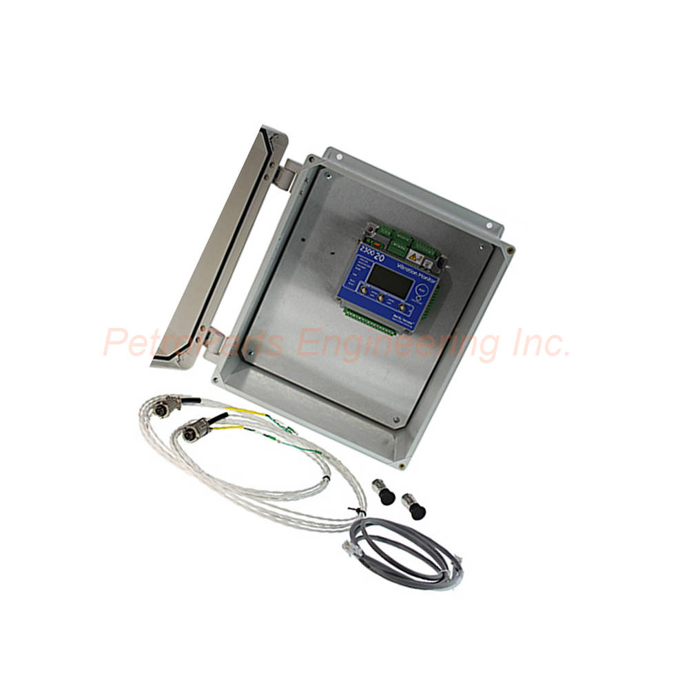
The Bently Nevada 2300/25_KIT-001-00 is a complete condition monitoring system kit. It includes a monitor, two sensors, cables, and a protective housing.
 Customer Reviews
UBEST Automation – Trusted Global Automation Parts Supplier
We offer a wide range of in-stock industrial automation spare parts. All products come with a 12-month warranty and a 30-day refund for quality issues.
Product Attributes:
Notice: For real-time prices and inventory, please click the button below to contact us.
Introduction to the Bently Nevada 2300/25 Condition Monitoring Kit
The 2300/25_KIT-001-00 from Bently Nevada is a complete condition monitoring system kit. This kit provides everything needed for machine protection monitoring. Engineers use the 2300/25_KIT-001-00 to measure vibration, speed, and temperature on rotating machinery. Its compact design suits both hazardous and non-hazardous locations. Furthermore, the kit includes two accelerometer sensors for immediate installation.
Kit Configuration Overview
Configuration 001 defines the specific contents of this kit. The 2300/25_KIT-001-00 includes one 2300/25 monitor as the core component. Two accelerometer sensors (model 200350) are provided for vibration measurement. Additionally, two 17 ft (5.2 m) cables (model 9571) connect the sensors to the monitor. A 6 ft (1.8 m) shielded Ethernet cable enables network communication. For housing, two options are available depending on the area classification. The kit excludes the Keyphasor sensor and 24V DC power supply.
Housing Options
Two housing options come with this kit based on configuration. For non-hazardous areas, the fiberglass housing (105M6193-01) is included. For hazardous areas, the stainless steel housing (105M6193-03) is provided instead. Housing dimensions measure 18.03 x 15.04 x 6.3 inches. These enclosures protect the monitor from environmental damage. Therefore, the 2300/25_KIT-001-00 suits various installation environments.
Power Input Specifications
The 2300/25_KIT-001-00 monitor accepts DC power input from 18 to 36 Vdc. Maximum power consumption is only 7.5 watts. This low power draw suits remote or solar-powered installations. The monitor requires a separate 24V DC power supply. Consequently, users must provide their own power source for operation.
Channel Types and Configuration
Multiple channel types are supported by the 2300/25 monitor. ICP accelerometers connect directly for vibration measurement. The bandpass filter is configurable from 0.2 Hz to 20 kHz. Scale factor range spans 5 to 1000 mV/g for flexibility. Full scale range reaches 2 to 80 g peak acceleration. For velocity measurements, scale factor ranges from 5 to 1000 mV/in/s. Radial vibration supports scale factors from 5 to 1000 mV/mil. Thrust channel scale factors also range from 5 to 1000 mV/mil. Independent 24-bit ADCs on each input channel ensure high accuracy. Overall accuracy stays within ±1% of full scale range for the 2300/25_KIT-001-00.
Speed and Keyphasor Input
Keyphasor transducers are supported for speed measurement. Multiple events per revolution can be processed by the monitor. Event ratios are configurable for speed inputs up to 20 kHz. Threshold voltage resolution reaches 0.1 Vdc for precise triggering. RPM range extends from 1 to 120,000 revolutions per minute. Therefore, the 2300/25_KIT-001-00 handles high-speed machinery applications.
Proximity Transducer Interface
The proximity transducer interface provides a supply voltage from -22.8 to -25.2 Vdc. Maximum rated current reaches 15 mA for connected sensors. Short circuit current ranges from 15.1 mA to 23.6 mA for protection. Accuracy holds at ±1% of full scale range. Input impedance measures 10 kΩ for 3-wire voltage mode. For proximity switch interface, supply voltage ranges from -10 to -24 Vdc. The lower not OK limit is set at -2.75 ±0.05 V. RPM range for proximity switches spans 1 to 60,000 rpm.
Other Input Types
Magnetic pickups are also supported by the 2300/25_KIT-001-00. Input voltage adapts to sensor model 284947 output characteristics. RPM range for magnetic pickups spans 200 to 120,000 rpm. Three contact inputs provide additional monitoring capabilities. These contacts support configuration lock, latched alarm reset, and monitor bypass functions. Activation requires 0 to 10 kΩ resistance. De-activation occurs from 150 kΩ to infinite resistance. An external button also resets latched alarms and relays.
Outputs and Relays
Three buffered outputs are available through BNC connectors on the monitor. Two vibration outputs provide raw signal access for analysis. One speed output delivers tachometer signals to other systems. Relays provide two dry-contact outputs for external alarm indication. These relays may be normally energized or de-energized by configuration. Contact life reaches 100,000 cycles at 5 amps, 250 Vac. For DC loads, 200,000 cycles at 1 amp, 24 Vdc is typical. Maximum switched contact voltage is 250 Vac or 250 Vdc. Maximum breaking contact current reaches 6 A at 250 Vac or 6 A at 24 Vdc. For hazardous areas, maximum switched values are derated appropriately.
SPA Output Specifications
The SPA output on the 2300/25_KIT-001-00 provides additional signal capabilities. Input signal range includes High AC at 8 Vpp and Low AC at 1.6 Vpp. DC GAP range spans 0 to -20 Vdc. Accuracy for High/Low AC is ±1% of full scale at 100 Hz. DC GAP accuracy is ±0.5 V with measurable AC accuracy at ±20 mV. Frequency response ranges from 10 Hz to 3000 Hz within ±5%.
LED Indicators
Comprehensive LED indicators provide clear monitor status at a glance. The OK LED indicates when the monitor is operating properly. Protection fault LED signals hardware faults impacting alarm determination. User inhibit LED shows alarms and relays intentionally inhibited. Bypass LED indicates user-initiated bypass action. Relay status LED shows if relays have been activated. TX/RX LED indicates Ethernet status and remote software communication. SPEED/AUX channel status LED shows valid speed signal input. Alert LED engages if any channel is in alert state. Danger LED engages if any channel reaches danger state. The LCD display allows viewing machine speed, vibration values, setpoints, and configuration.
Communications
Ethernet communication uses 10Base-T and 100Base-TX standards. The interface conforms to IEEE802.3 specifications. An RJ-45 connector accepts standard Ethernet cabling. Maximum cable length reaches 100 meters (328 feet). The 2300/25_KIT-001-00 communicates with System 1 software for data analysis.
Environmental Limits
Operating temperature ranges from -30°C to +65°C (-22°F to +149°F). Storage temperature spans -40°C to +85°C (-40°F to +185°F). Humidity tolerance reaches up to 95% non-condensing. Vibration limitation is 3 g for reliable operation. Battery life for the real-time clock reaches 38 years powered at 50°C. Un-powered battery life extends to 12 years at 50°C. Therefore, the 2300/25_KIT-001-00 suits harsh industrial environments.
Data Storage Capabilities
Trend measurements are stored at configurable intervals. Pre-event data stores 10 minutes at 1 second intervals. Additional pre-event data stores 20 seconds at 100 millisecond intervals. Post-event data stores 10 seconds at 100 millisecond intervals. One minute of post-event data stores at 1 second intervals. Spectrums and waveforms also have dedicated storage. Pre-event spectra store 2.5 minutes at 10 second intervals. Post-event spectra store 1 minute at 10 second intervals. During network disruptions, the 2300 stores at least 5 alarm data captures. This requires System 1 Evolution 21.1 or newer and firmware release 3.2 or newer.
Physical Dimensions
Dimensions measure 127 mm wide by 127 mm deep by 76.2 mm high. In imperial units, this equals 5 x 5 x 3 inches. Weight is 1.03 kg or 2.26 lbs. Mounting options include panel mount or DIN rail. A DIN rail adapter is included with the 2300/25_KIT-001-00.
Installation Guidelines
Follow these steps to install the 2300/25_KIT-001-00 correctly.
Mount the Housing: Secure the fiberglass or stainless steel housing to a rigid surface. Ensure adequate clearance for cable entry and ventilation.
Install the Monitor: Mount the 2300/25 monitor inside the housing using panel or DIN rail. The adapter is included for DIN rail mounting.
Mount Accelerometers: Install the two 200350 accelerometers on the machine measurement points. Use proper surface preparation and mounting torque.
Connect Cables: Attach the 9571 cables between accelerometers and monitor. Also connect the shielded Ethernet cable to your network switch.
Wire Power: Connect 18-36 Vdc power to the monitor terminals. Do not exceed 7.5 watts maximum power consumption.
Configure Channels: Use the LCD display or System 1 software to configure each channel. Set scale factors, full scale ranges, and filter frequencies for the 2300/25_KIT-001-00.
Set Alarms: Configure alert and danger setpoints for each measurement channel. Also set relay behavior for alarm conditions.
Test Operation: Apply power and verify all LEDs indicate normal operation. Inject test signals to confirm alarm and relay functionality.
Package Contents
Your 2300/25_KIT-001-00 shipment includes the following items:
One Bently Nevada 2300/25 condition monitor
One fiberglass or stainless steel housing (105M6193-01 or -03)
Two 200350 accelerometer sensors
Two 9571 cables (17 ft / 5.2 m each)
One shielded Ethernet cable (6 ft / 1.8 m)
One DIN rail mounting adapter
One installation instruction sheet
Common FAQs
1. Does the 2300/25_KIT-001-00 include a power supply?
No, the 2300/25_KIT-001-00 excludes the 24V DC power supply. Users must provide their own 18-36 Vdc power source.
2. What is the difference between the two housing options?
Fiberglass housing (105M6193-01) suits non-hazardous areas only. Stainless steel housing (105M6193-03) is certified for hazardous area installation.
3. Can I add more sensors to this kit configuration?
Configuration 001 includes exactly 2 sensors and 1 housing. For additional sensors, order a different configuration or add components separately to the 2300/25_KIT-001-00.
4. What software is required to configure this monitor?
Use Bently Nevada System 1 Evolution software version 21.1 or newer. Alternatively, configure directly using the front panel LCD display.
5. How many alarm events can the 2300 store during network loss?
The monitor stores at least 5 alarm data captures during network disruption. This requires System 1 Evolution 21.1+ and firmware 3.2+ for the 2300/25_KIT-001-00.
Conclusion
The Bently Nevada 2300/25_KIT-001-00 delivers comprehensive condition monitoring in one complete package. Its two accelerometers and protective housing simplify field installation. Multiple channel types support vibration, speed, and proximity measurements. The compact design fits panel or DIN rail mounting. For turnkey machine protection, choose the 2300/25_KIT-001-00 condition monitoring system kit.
Welcome to learn about our business. We are a leading global provider of automation equipment and will provide you with complete and cost-effective product solutions. You are welcome to choose us, and our services will make you a long-term partner like our other customers.
Now please let us know your needs and suggestions.
About Ubest
Ubest Automation is a leading global provider of automation products, with deep partnerships with major automation manufacturers to provide customers with customized business solutions, cost-effective products, and comprehensive services.
Product Center
Contact Us
Phone:+86 180 3000 5825
Address:Room 7A, No. 59 Hubin North Road, Siming District Xiamen City China
Email: [email protected]
Contact: Klaus
Industry Links
© 2026, Ubest Automation Limited All Rights Reserved. sitemap