
Allen-Bradley 1794-IV32 Input Module | 32 Points 24V
Introduction:
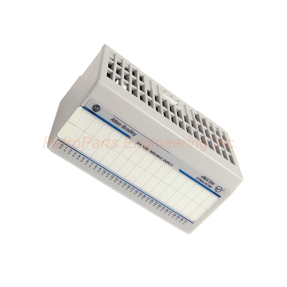
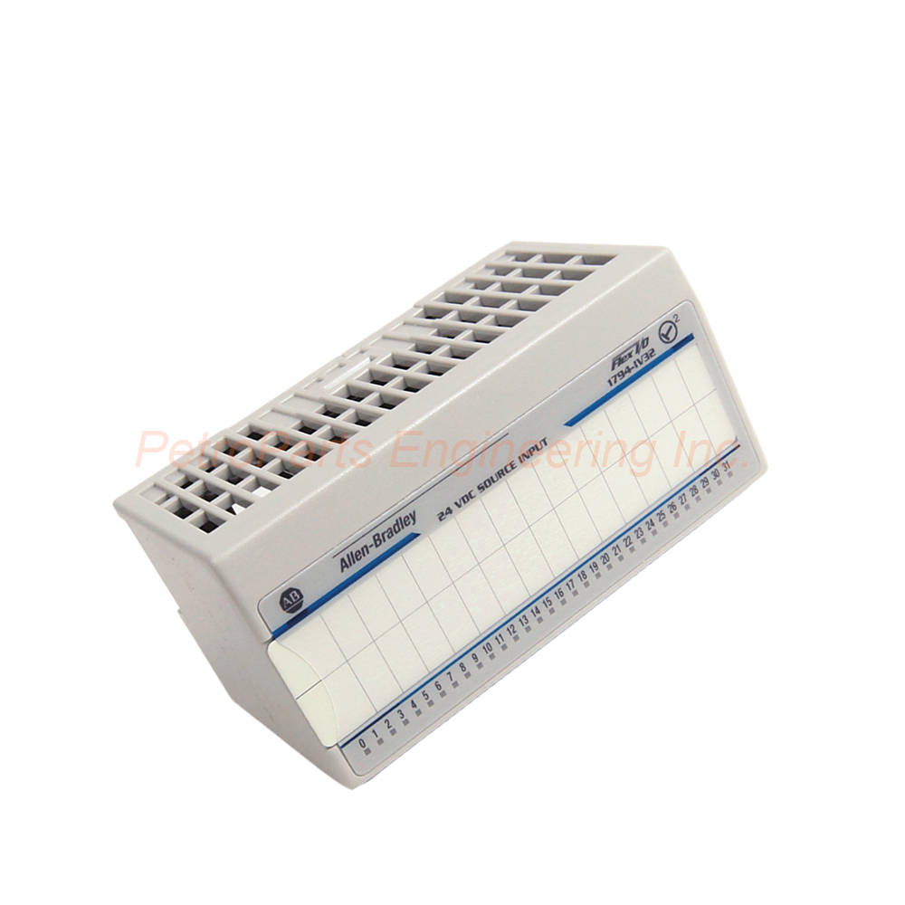
The Allen-Bradley 1794-IV32 provides 32 high-density DC inputs for Flex I/O systems. Features 24V operation, configurable filter times, and 32 yellow status indicators.
 Customer Reviews
UBEST Automation – Trusted Global Automation Parts Supplier
We offer a wide range of in-stock industrial automation spare parts. All products come with a 12-month warranty and a 30-day refund for quality issues.
Product Attributes:
Notice: For real-time prices and inventory, please click the button below to contact us.
Allen-Bradley 1794-IV32 High Density DC Input Module for Flex I/O Systems
The Allen-Bradley 1794-IV32 is a discrete input module from the Flex I/O platform. This module features thirty-two (32) current sourcing input channels. Specifically, the 1794-IV32 accepts nominal input signal voltage of 24 VDC. Engineers use this high-density module for distributed I/O topology. Switches, auxiliary contacts, sensors, and binary operating devices all connect easily.
Product Overview and Functionality
The 1794-IV32 installs along with a Flex I/O assembly. A Flex I/O communication adapter serves as the header module. Data within the module's local memory transfers via the Flex I/O bus. The host controller receives this data through a communication highway. Consequently, distributed I/O becomes simple and cost-effective.
Input Voltage Specifications
The nominal input voltage is 24 VDC for standard applications. The input voltage range spans from 19.2 to 31.2 VDC. The minimum ON-state voltage reaches 19.2 VDC. The maximum ON-state voltage reaches 31.2 VDC. These clear thresholds ensure reliable state detection in industrial environments.
Input Current Specifications
The nominal ON-state current reaches 4.1 mA at 24V DC. The minimum ON-state current reaches 2.0 mA for reliable detection. The maximum ON-state current reaches 6.0 mA at full voltage. This current range suits standard 24V DC input devices. The wiring configuration uses source wiring (current sourcing).
Configurable Input Filter Times
The 1794-IV32 offers eight configurable input filter times. Available settings include 0.25 ms, 0.5 ms, 1 ms, 2 ms, 4 ms, 8 ms, 16 ms, and 32 ms. The default filter time is 0.25 ms for fast response. Use longer filter times to eliminate false activation from contact bounce. Filter times also reject electrical noise on input signals.
FlexBus Current Draw
The 1794-IV32 draws 40 mA at 5.1V DC from the FlexBus backplane. This power comes from the Flex I/O system without external wiring. The backplane current draw is 40 mA at 5.1V. Ensure your total I/O power draw stays within the adapter's capacity.
Status Indicators
The module has 32 yellow status indicator lights for input monitoring. Each indicator lights when the corresponding input channel is active. These LEDs alert users to different operating conditions. Troubleshooting field wiring issues becomes quick and simple.
Terminal Base Compatibility
The 1794-IV32 works with several terminal base units. Compatible bases include 1794-TB32, 1794-TB32S, 1794-TB62DS, and 1794-TB62EXD4X15. The keyswitch positions the module correctly on the mounting base. Technicians must turn the keyswitch until pins align with terminal base connectors.
Module Installation Features
The module includes several mechanical installation features. An alignment bar and groove make module alignment easier. A latching mechanism secures the module on its mounting base. The 1794-IV32 locks in place when the latch clicks. These features ensure proper seating and reliable operation.
Isolation Voltage and Dielectric Testing
The continuous isolation voltage reaches 50V for basic insulation type. The module has been type tested at 850V DC for 60 seconds. This testing occurs between field side and system circuits. Your control system gains protection from field wiring faults.
Environmental Ratings
The 1794-IV32 is made for indoor use only. Do not use this module in residential environments. The maximum pollution level accepts Pollution Degree 2. The overvoltage level accepts Overvoltage Category II. The maximum altitude reaches 6562 feet for installation.
Physical Dimensions
The dimensions measure 3.7 x 3.7 x 2.7 inches (94 x 94 x 69 mm). The compact size saves valuable cabinet space. Multiple high-density modules fit into a small footprint area. The module is grounded through a zinc-plated chromate-passivated steel DIN rail.
Controller Compatibility
The 1794-IV32 works with several controller platforms. Compatible controllers include PLC5, SLC 500, CompactLogix, and ControlLogix. The communication adapter determines the network protocol. Choose the appropriate adapter for your controller type.
Cleaning and Maintenance
Clean the module when necessary with a dry anti-static cloth. Use only soft fabric materials for cleaning. Do not expose the module to water or cleaning agents. Especially avoid caustic cleaning agents that may damage components.
Step-by-Step Installation Guide
Follow these steps to install your Allen-Bradley 1794-IV32 correctly.
Step 1: Select the Terminal Base
First, choose a compatible terminal base for your application. Options include 1794-TB32, 1794-TB32S, 1794-TB62DS, or 1794-TB62EXD4X15. Mount the terminal base on DIN rail securely. Use zinc-plated chromate-passivated steel DIN rail for proper grounding.
Step 2: Set the Keyswitch
Next, locate the keyswitch on the 1794-IV32 module. Turn the keyswitch until pins align with terminal base connectors. The keyswitch position prevents incorrect module insertion. Verify the keyswitch is fully engaged before proceeding.
Step 3: Install the Module
Now, use the alignment bar and groove to guide the module. Insert the 1794-IV32 into the mounted terminal base. Push firmly until the latching mechanism clicks into place. Ensure the module sits flush with adjacent units.
Step 4: Connect Field Wiring
Wire your 24V DC field devices to the terminal base screw terminals. Use source wiring configuration for all input connections. Connect each input signal to the appropriate channel number. Tighten all connections to the specified torque value.
Step 5: Configure Filter Times
Access your control system configuration software for the 1794-IV32. Select the appropriate input filter time for each channel. Use 0.25 ms for fast response applications. Use longer filter times for noisy environments or mechanical switches.
Step 6: Test Input Operation
Apply power to the Flex I/O system and observe the yellow status indicators. Activate each field device to verify input detection. The yellow LED should light when the input is ON. Then, deactivate each device to verify OFF state detection. Confirm the input status in your controller.
Complete Package Contents
Your Allen-Bradley 1794-IV32 shipment includes the following items:
Allen-Bradley 1794-IV32 Discrete Input Module (1 unit)
Product documentation and installation manual
Module labeling sheet for channel identification
Keyswitch adjustment tool
Note: Shipping partners include FedEx, UPS, and DHL.
Frequently Asked Questions (FAQ)
Q1: How many input channels does the 1794-IV32 provide?
The 1794-IV32 provides 32 high-density input channels. Each channel has a dedicated yellow status indicator. The module accepts 24V DC sourcing inputs only.
Q2: What filter times are available on the 1794-IV32?
The 1794-IV32 offers eight configurable filter times. These include 0.25, 0.5, 1, 2, 4, 8, 16, and 32 ms. The default filter time is 0.25 ms for fast response.
Q3: What is the FlexBus current draw of this module?
The 1794-IV32 draws 40 mA at 5.1V DC from the FlexBus backplane. This power comes from the Flex I/O system automatically. No external power connection is required for the module logic.
Q4: What terminal bases work with the 1794-IV32?
The 1794-IV32 works with 1794-TB32, 1794-TB32S, 1794-TB62DS, and 1794-TB62EXD4X15 bases. Choose the base that matches your wiring and environmental requirements.
Q5: What is the isolation voltage rating of the 1794-IV32?
The continuous isolation voltage reaches 50V for basic insulation. The module is type tested at 850V DC for 60 seconds. This testing occurs between field side and system circuits.
Welcome to learn about our business. We are a leading global provider of automation equipment and will provide you with complete and cost-effective product solutions. You are welcome to choose us, and our services will make you a long-term partner like our other customers.
Now please let us know your needs and suggestions.
About Ubest
Ubest Automation is a leading global provider of automation products, with deep partnerships with major automation manufacturers to provide customers with customized business solutions, cost-effective products, and comprehensive services.
Product Center
Contact Us
Phone:+86 180 3000 5825
Address:Room 7A, No. 59 Hubin North Road, Siming District Xiamen City China
Email: [email protected]
Contact: Klaus
Industry Links
© 2026, Ubest Automation Limited All Rights Reserved. sitemap