
Yokogawa AAR145-S00 Input Module 16 Channel RTD POT Isolated
Introduction:
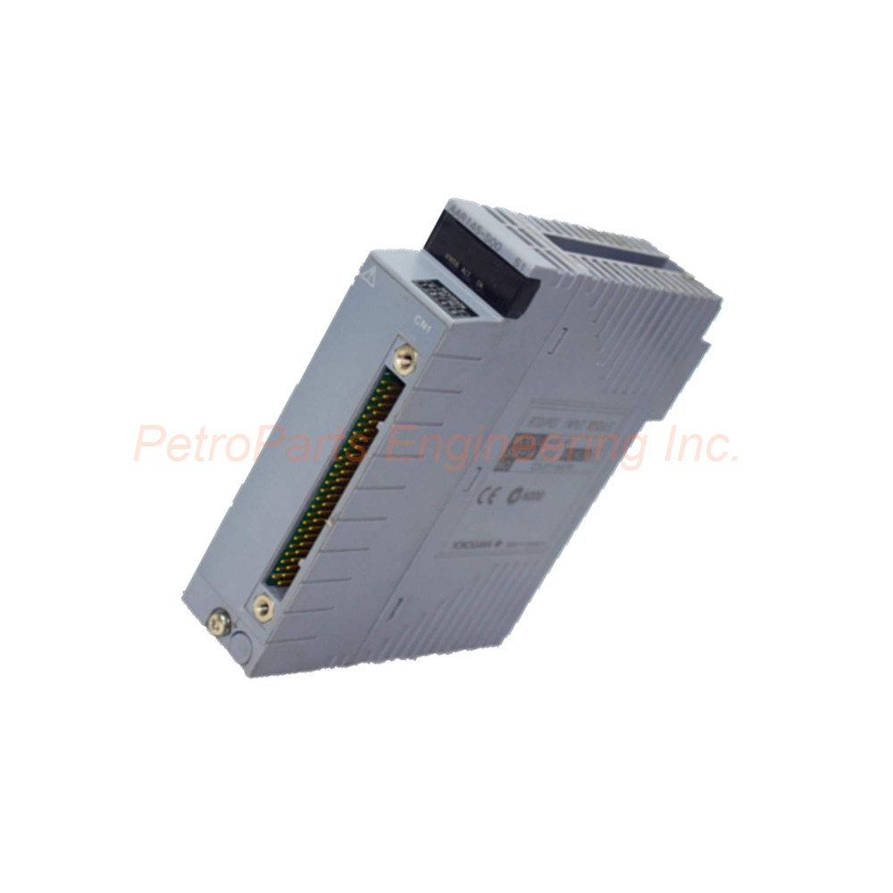
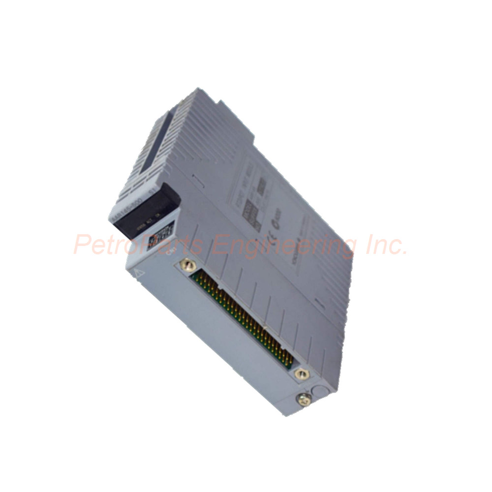
The AAR145-S00 is a 16-channel input module from Yokogawa for RTD and POT signals. It features fully isolated channels and supports Pt100 3-wire RTDs. This module also accepts potentiometer inputs from 100Ω to 10kΩ.
 Customer Reviews
UBEST Automation – Trusted Global Automation Parts Supplier
We offer a wide range of in-stock industrial automation spare parts. All products come with a 12-month warranty and a 30-day refund for quality issues.
Product Attributes:
Notice: For real-time prices and inventory, please click the button below to contact us.
Product Overview
The AAR145-S00 belongs to the AAR Series product line. Its product type is an Input Module with 16 Channels for RTD/POT. The product classification is I/O Modules. The current price for this item is ¥6,250 RMB, and the product gross weight is 0.30 kg.
Yokogawa designed this input module for temperature and position measurement applications. The AAR145-S00 accepts RTD (Pt100) and potentiometer (POT) input signals across 16 isolated channels. Users can select RTD or POT input individually for each channel from CH1 to CH16. The module requires a dedicated cable (KS8/AKB335) and connects to terminal boards such as MRT, TERT, or AER4D. Therefore, this module suits distributed control systems requiring multiple RTD or potentiometer inputs.
Technical Specifications
Input Channels
The module provides 16 input channels , and all channels feature isolation from each other. This isolation prevents interference between channels and protects against ground loops. Consequently, the AAR145-S00 delivers reliable measurements even in electrically noisy industrial environments.
RTD Input Specifications
For RTD input, the module accepts Pt100 sensors conforming to JIS C1604:1997 and IEC751:1995 standards. The module supports 3-wire type connections, which compensates for lead wire resistance. The measurement current is 1 mA , minimizing self-heating effects. Accuracy reaches ±150 mΩ , providing precise temperature measurements.
Potentiometer Input Specifications
For potentiometer input, the module accepts total resistance values from 100 Ω to 10 kΩ . The span resistance must be 50% or larger of the total resistance. Accuracy reaches ±0.2% of full scale . Therefore, this module suits position feedback and manual setpoint applications.
Input Signal Selection
Users can switch input signals individually for each channel from CH1 to CH16. This flexibility allows mixing RTD and POT inputs within the same module. For example, channels 1-8 can measure RTD temperatures while channels 9-16 read potentiometer positions.
Voltage and Withstanding Ratings
The allowable input voltage is ±5 V . Withstanding voltage between input and system reaches 500 V AC for 1 minute (1500 V AC for single card configurations). Between input channels, the withstanding voltage is 200 V AC for 1 minute . These high isolation ratings ensure operator safety and equipment protection.
Input Resistance
The input resistance measures 1 MΩ or larger when power is ON. Similarly, when power is OFF, the input resistance remains 1 MΩ or larger . This high impedance minimizes loading on the connected sensors.
Wiring Resistance Limits
The allowable total resistance of the signal source plus wiring is 150 Ω or less per wire . This limit applies specifically to wiring resistance per wire. For RTD 3-wire connections, keep each lead wire resistance below 150Ω for accurate measurements.
Data Update Period
The data update period is 1 second . This update rate suits most temperature and position monitoring applications. For faster response requirements, consider alternative modules with shorter update periods.
Burn-Out Detection
The burn-out detection feature applies to all channels together . Users can set this function to not available or available with UP/DOWN direction. The detection time is 60 seconds . When enabled, the module detects sensor wire breaks and drives the output to a user-selectable upscale or downscale value.
Temperature Drift
The temperature drift for RTD input is ±0.3 Ω per 10°C . For potentiometer input, the drift is ±0.4% per 10°C . These low drift values ensure stable measurements across varying ambient temperatures.
Power Consumption
The maximum current consumption is 350 mA at 5 V DC . This low power draw minimizes load on the system power supply. Multiple AAR145-S00 modules can operate together within the chassis power budget.
External Connection
The module requires a dedicated cable (KS8/AKB335) for external connections. Compatible terminal boards include MRT, TERT, and AER4D . Always use Yokogawa-approved cables and terminal boards for reliable operation.
Suffix Codes
The suffix code -S indicates the standard type . The next code 0 specifies no explosion protection . The final code 0 designates the basic type . Therefore, the AAR145-S00 suits standard industrial environments without hazardous area requirements.
Installation Guide
Follow these steps to install your AAR145-S00 correctly.
Power Down the System: Disconnect power from the chassis. This prevents electrical damage during installation.
Select a Slot: Choose an available I/O slot in your Yokogawa system. Ensure adequate clearance for wiring.
Insert the Module: Align the AAR145-S00 with the slot guides. Push firmly until the module seats into the backplane connector.
Secure the Module: Tighten the retaining screws at the top and bottom. This secures the input module in place.
Connect the Terminal Board: Attach the appropriate terminal board (MRT, TERT, or AER4D ) using the dedicated KS8/AKB335 cable.
Wire Sensors: Connect Pt100 RTDs (3-wire) or potentiometers to the terminal board. Keep each wire resistance below 150 Ω .
Configure Channels: Set each channel for RTD or POT input using your system configuration software. Select burn-out settings as needed.
Apply Power: Restore power to the chassis. Verify the module powers up without errors.
Verify Readings: Check input values from all 16 channels. Confirm accuracy meets your application requirements.
Package List
1 x AAR145-S00 Input Module (16 channel, RTD/POT)
1 x Module retaining screws set (pre-installed)
1 x Installation instruction manual
*Note: Dedicated cable (KS8/AKB335) and terminal board (MRT/TERT/AER4D) are sold separately.*
Frequently Asked Questions (FAQ)
1. Can I mix RTD and POT inputs on the same AAR145-S00 module?
Yes, you can select RTD or POT input individually for each channel from CH1 to CH16. This flexibility allows mixing sensor types within one module.
2. What is the maximum wiring resistance allowed for RTD connections?
The allowable total resistance of signal source plus wiring is 150 Ω or less per wire . For 3-wire RTDs, keep each lead wire resistance below this limit to maintain specified accuracy.
3. Does this module support 2-wire or 4-wire RTD connections?
The AAR145-S00 specifically supports 3-wire type RTD connections according to JIS C1604 and IEC751 standards. For 2-wire or 4-wire applications, consider other Yokogawa input modules.
4. What happens when the module detects a sensor wire break?
When burn-out detection is enabled, the module detects sensor breaks within 60 seconds . It then drives the output to either UPSCALE or DOWNSCALE based on your configuration setting.
5. What terminal boards work with the AAR145-S00 ?
This module connects to MRT, TERT, or AER4D terminal boards using the dedicated KS8/AKB335 cable. Always use Yokogawa-approved components for proper compatibility and safety.
Welcome to learn about our business. We are a leading global provider of automation equipment and will provide you with complete and cost-effective product solutions. You are welcome to choose us, and our services will make you a long-term partner like our other customers.
Now please let us know your needs and suggestions.
About Ubest
Ubest Automation is a leading global provider of automation products, with deep partnerships with major automation manufacturers to provide customers with customized business solutions, cost-effective products, and comprehensive services.
Product Center
Contact Us
Phone:+86 180 3000 5825
Address:Room 7A, No. 59 Hubin North Road, Siming District Xiamen City China
Email: [email protected]
Contact: Klaus
Industry Links
© 2026, Ubest Automation Limited All Rights Reserved. sitemap