
Allen-Bradley 1794-IM8 AC Input Module | 8 Points 240V
Introduction:
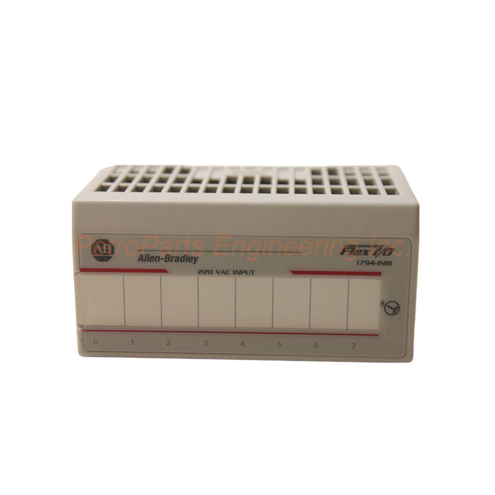
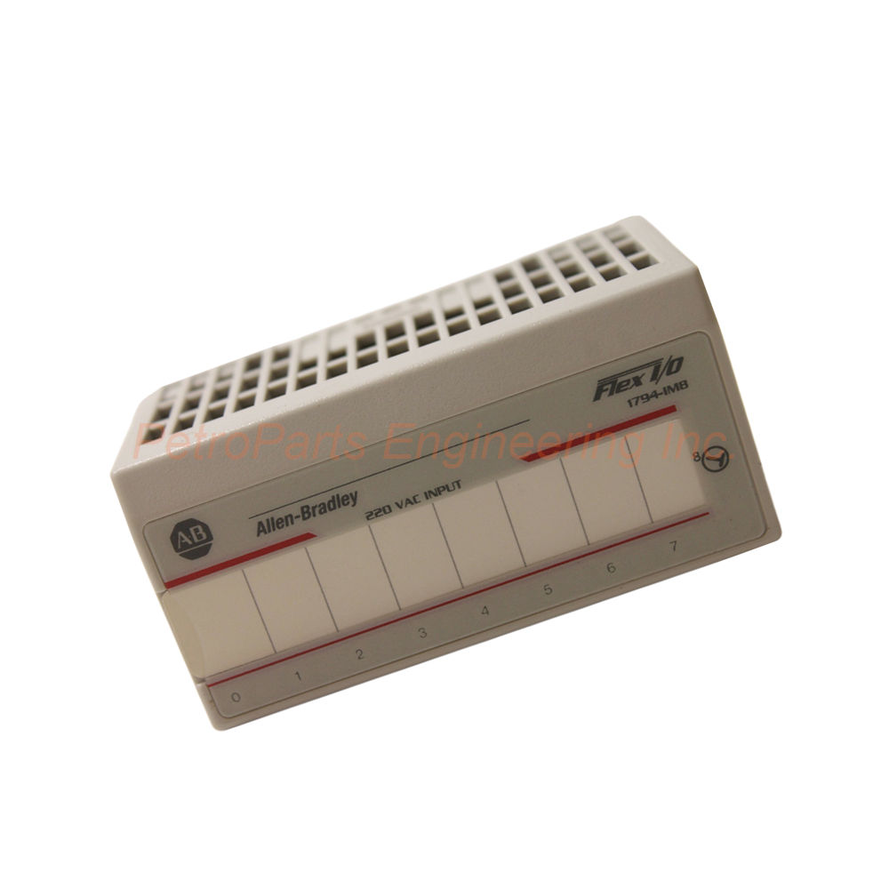
The Allen-Bradley 1794-IM8 provides 8 AC digital inputs for Flex I/O systems. Features 240V AC operation, 22.3 kΩ impedance, and hazardous location approval.
 Customer Reviews
UBEST Automation – Trusted Global Automation Parts Supplier
We offer a wide range of in-stock industrial automation spare parts. All products come with a 12-month warranty and a 30-day refund for quality issues.
Product Attributes:
Notice: For real-time prices and inventory, please click the button below to contact us.
Allen-Bradley 1794-IM8 220V AC Digital Input Module for Flex I/O Systems
The Allen-Bradley 1794-IM8 is a 240 Volt AC input module from Rockwell Automation. This unit belongs to the Flex I/O system family. Specifically, the 1794-IM8 works on a rack-based configuration of modules. The Flex I/O system consists of three main parts: a terminal unit, an adapter, and an I/O module. Engineers use this module for high voltage AC input monitoring in industrial applications.
Input Channel Specifications
The 1794-IM8 provides 8 non-isolated input channels. The nominal ON-state voltage reaches 240V AC for standard operation. The maximum ON-state current reaches 13.21 mA per channel. The nominal input current reaches 12 mA at 240V AC. These specifications suit direct connection to 220-240V AC field devices.
OFF-State Characteristics
The maximum OFF-state voltage reaches 40V AC for reliable detection. The maximum OFF-state current reaches 2.6 mA when the input is off. These clear thresholds ensure proper state detection. Noise immunity remains high with these specifications.
Input Impedance
The nominal input impedance reaches 22.3 kΩ for this module. This high impedance minimizes loading on field devices. Your switches and sensors see minimal current draw. Consequently, contact life extends in many applications.
Isolation Voltage
The isolation voltage reaches 250V Continuous for circuit protection. All inputs are individually insulated from the system. The backplane type tested each channel individually. Your control system gains protection from high voltage field wiring.
FlexBus Current Draw
The 1794-IM8 draws 30 mA at 5V DC from the FlexBus backplane. This power comes from the Flex I/O system automatically. Ensure your total I/O power draw stays within the adapter's capacity.
Thermal Dissipation
The thermal dissipation reaches 16.2 BTU/hr at 264V AC maximum. This low heat generation suits high-density installations. Account for this heat in your enclosure cooling calculations. Multiple modules generate manageable heat levels.
Terminal Base Compatibility
A 1794-TBN terminal base works with the 1794-IM8 module. The terminal base provides screw connections for field wiring. The module has dedicated wiring labels for easy connection. The terminal base also supports daisy-chain power distribution.
Keyswitch Position
The 1794-IM8 has 8 keyswitch positions in total. Set the keyswitch correctly during installation. This prevents incorrect module insertion into the wrong base. Your system gains protection from mismatched modules.
Enclosure and Mounting
The module supports an open style enclosure for installation. Two mounting methods are available for flexibility. Choose screw mounting or DIN rail mounting as needed. The small size fits easily into crowded cabinets.
Physical Dimensions
The dimensions measure 94 x 94 x 91 millimeters (3.7 x 3.7 x 3.6 inches). This compact size allows easy transportation and storage. Multiple modules fit into a small footprint area. The module installs quickly in any Flex I/O rack.
Operating Temperature Range
The operating temperature ranges from 0 to 55 °C (32 to 131 °F). The module functions reliably within this range. Install in well-ventilated areas for best performance. Avoid mounting near heat-generating equipment.
Hazardous Location Approval
The 1794-IM8 is approved for operation in hazardous locations. Check your specific approval documentation for ratings. This expands application possibilities for this module. Oil and gas facilities benefit from this approval.
Inrush Current and Fusing
The maximum voltage upon startup reaches 10A briefly. The module must receive appropriate power at all times. Fuses should be installed to avoid damage to the device. Size fuses according to your local electrical code.
Installation Notes
The FlexBus must be properly inserted for module operation. The module will not work until fully connected. All connections should be secure before applying power. Verify the terminal base locks firmly to the DIN rail.
Step-by-Step Installation Guide
Follow these steps to install your Allen-Bradley 1794-IM8 correctly.
Step 1: Select the Terminal Base
First, choose a 1794-TBN terminal base for this module. Mount the terminal base on DIN rail or using screws. Ensure proper grounding of the base unit. Use zinc-plated steel DIN rail for reliable grounding.
Step 2: Set the Keyswitch
Next, locate the keyswitch on the 1794-IM8 module. Set the keyswitch position to the correct setting for this module. This prevents incorrect insertion into the wrong slot. Verify the keyswitch is fully engaged before proceeding.
Step 3: Install the Module
Now, insert the 1794-IM8 into the mounted terminal base. Push firmly until the module seats completely. The FlexBus connector must engage properly. Ensure the module will not work until fully connected.
Step 4: Connect Field Wiring
Wire your 220-240V AC field devices to the terminal base. Connect each input signal to the appropriate channel number. Follow the dedicated wiring labels on the terminal base. Tighten all connections to the specified torque value.
Step 5: Install Fuses
Install appropriate fuses on each input circuit for protection. The maximum startup voltage reaches 10A briefly. Size fuses based on your actual load requirements. Fuses prevent damage from overcurrent conditions.
Step 6: Test Input Operation
Apply power to the Flex I/O system and observe operation. Activate each AC field device to verify input detection. Check the input status in your controller. Then, deactivate each device to verify OFF state detection. Confirm the module functions within the 0-55°C temperature range.
Complete Package Contents
Your Allen-Bradley 1794-IM8 shipment includes the following items:
Allen-Bradley 1794-IM8 AC Digital Input Module (1 unit)
Product documentation and installation manual
Module labeling sheet for channel identification
Keyswitch adjustment tool
Note: Shipping partners include FedEx, UPS, and DHL.
Frequently Asked Questions (FAQ)
Q1: How many input channels does the 1794-IM8 provide?
The 1794-IM8 provides 8 non-isolated AC input channels. The nominal ON-state voltage is 240V AC. Each channel has a nominal input current of 12 mA at 240V AC.
Q2: What is the input impedance of the 1794-IM8?
The nominal input impedance reaches 22.3 kΩ for this module. This high impedance minimizes loading on field devices. Contact life extends due to the low current draw.
Q3: What terminal base works with the 1794-IM8?
A 1794-TBN terminal base works with the 1794-IM8 module. The terminal base provides screw connections for field wiring. The base also supports daisy-chain power distribution.
Q4: Is the 1794-IM8 approved for hazardous locations?
Yes, the 1794-IM8 is approved for operation in hazardous locations. Check your specific approval documentation for exact ratings. This approval expands application possibilities for this module.
Q5: What fusing is recommended for the 1794-IM8?
Fuses should be installed on each input circuit for protection. The maximum startup voltage reaches 10A briefly. Size fuses according to your local electrical code and load requirements. Fuses prevent damage from overcurrent conditions.