
HIMA X-AI3201 Analog Input Module 32 Channels SIL 3


Introduction:
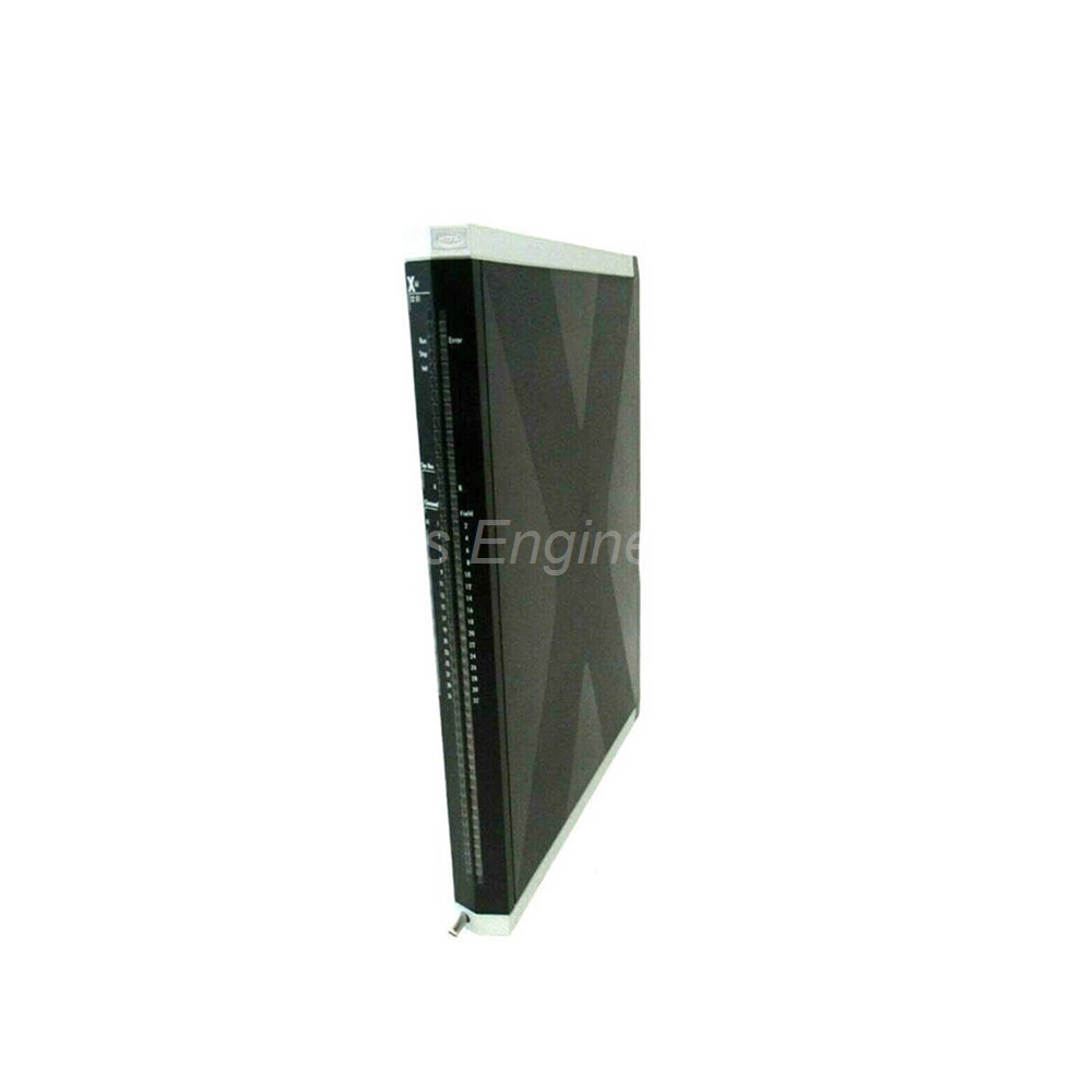
HIMA X-AI3201 analog input module. 32 channels, 0/4-20 mA, 12-bit resolution, SIL 3 certified. With 32 transmitter supplies. For HIMax.
 Customer Reviews
UBEST Automation – Trusted Global Automation Parts Supplier
We offer a wide range of in-stock industrial automation spare parts. All products come with a 12-month warranty and a 30-day refund for quality issues.
Product Attributes:
Notice: For real-time prices and inventory, please click the button below to contact us.
Product Overview
The HIMA X-AI3201 is a high-density analog input module for HIMax systems. This module evaluates up to 32 analog input signals from field devices. It is TÜV-certified for safety applications up to SIL 3. The X-AI3201 includes 32 individual transmitter supplies for loop-powered sensors. You get reliable current measurement for critical process control.
Technical Specifications
General Power Data
-
Supply Voltage: 24 VDC with -15 % to +20 % tolerance.
-
Ripple (rP): ≤ 5 %, SELV, PELV compliant.
-
Current Input Minimum: 500 mA (without channels or transmitter supplies).
-
Current Input Maximum: 1.5 A (if transmitter supplies are short-circuited).
-
Current per Channel: 0 mA minimum (without transmitter supply).
-
Current per Channel: 30 mA minimum (with transmitter supply).
Environmental Limits
-
Operating Temperature: 0 °C to +60 °C.
-
Storage Temperature: -40 °C to +85 °C.
-
Relative Humidity: Max 95 %, non-condensing.
-
Type of Protection: IP20.
-
Safety Certification: SIL 3 (IEC 61508, IEC 61511, IEC 62061).
-
Safety Certification: Category 4 and PL e (EN ISO 13849-1).
Physical Characteristics
-
Dimensions (H x W x D): 310 mm x 29.2 mm x 230 mm.
-
Weight: Approximately 1.4 kg.
-
Rack Slots: Any slot except system bus module slots.
-
Galvanic Isolation: Inputs isolated from system bus and 24 V supply.
Analog Input Specifications
-
Number of Channels: 32 inputs with common ground AI-.
-
Nominal Range: 0/4 to 20 mA.
-
Operating Range: 0 to 22.5 mA.
-
Digital Resolution: 12-bit.
-
Shunt Resistance: 200 Ω for current measurement.
-
Maximum Permitted Current: 50 mA via shunt.
-
Withstand Voltage: ≤ 10 VDC at input.
-
Interference Suppression: > 60 dB common mode at 50/60 Hz.
-
Measured Value Renewal: Cycle time of the user program.
-
Sampling Time: 2 ms.
-
Metrological Accuracy: ± 0.15 % of final value over -10 °C to 70 °C.
-
Settling Time: 15 ms to 99 % of process value.
Transmitter Supply Specifications
-
Number of Supplies: 32 individual transmitter supplies.
-
Output Voltage: 26.5 VDC with +0 / -15 % tolerance.
-
Output Current: Maximum 30 mA per supply.
-
Undervoltage Monitoring: 22.5 VDC trip point.
-
Overvoltage Monitoring: 30 VDC trip point.
-
Short Circuit Limit: 12 supplies may be shorted simultaneously.
-
Overload Protection: Entire supply shuts off if 12+ supplies short for 3 seconds.
-
Automatic Recovery: Supply restarts if overload clears within 30 seconds.
-
Maximum Load: ≤ 750 Ω at 22.5 mA (transmitter plus line resistance).
System Cable X-CA 005
The X-CA 005 system cable connects the X-AI3201 to field termination assemblies. This cable works with X-CB 008 03/04 connector boards.
-
Cable Type: LIYCY-TP 38 x 2 x 0.25 mm².
-
Wire Construction: Finely stranded.
-
Average Outer Diameter: Approximately 16.8 mm.
-
Maximum Diameter: 20 mm for all cable types.
-
Minimum Bending Radius (Fixed): 5 x diameter.
-
Minimum Bending Radius (Flexible): 10 x diameter.
-
Combustion Behavior: Flame resistant and self-extinguishing per IEC 60332-1-2 and -2-2.
-
Available Lengths: 5 to 30 metres.
Installation Guide
Follow these steps to install the HIMA X-AI3201 correctly. First, insert the module into any base plate slot except system bus slots. Second, connect the 24 VDC supply with proper SELV/PELV isolation. Third, wire each analog input to the 200 Ω shunt using twisted pair cables. Fourth, connect up to 32 transmitters to the individual 26.5 V supplies. Fifth, verify the load resistance does not exceed 750 Ω per channel. Sixth, use the X-CA 005 system cable to connect to field termination assemblies. Seventh, configure the nominal range (0-20 mA or 4-20 mA) in your HIMax project. Finally, test each channel with a calibrated current source before startup.
Package Contents
-
1 x HIMA X-AI3201 analog input module.
-
1 x Front panel with 32 channel indicators.
-
Note: X-CA 005 system cable ordered separately.
-
Note: X-CB 008 connector board ordered separately.
-
Note: No field termination assemblies included.
Frequently Asked Questions (FAQ)
Q1: What safety rating does the HIMA X-AI3201 carry?
A: The X-AI3201 is TÜV-certified for SIL 3 applications per IEC 61508, IEC 61511, and IEC 62061. It also meets Category 4 and PL e per EN ISO 13849-1. You can use it in emergency shutdown and burner management systems.
Q2: What happens if I short circuit more than 12 transmitter supplies on the HIMA X-AI3201?
A: If 12 or more supplies remain shorted for longer than 3 seconds, the entire transmitter supply section shuts down. The module automatically restarts the supplies if the overload clears within 30 seconds. This protects the module from permanent damage.
Q3: What is the maximum load resistance for each analog input channel?
A: The maximum connectable load (transmitter plus line resistance) is 750 Ω at 22.5 mA. The transmitter supply outputs 26.5 VDC which allows this load. Higher resistance will cause insufficient current for accurate measurement.
Q4: How fast does the HIMA X-AI3201 update measured values?
A: The sampling time is 2 ms per channel. The measured value renewal follows the user program cycle time. The settling time to 99 % of process value is 15 ms when the input signal changes.
Q5: Can I use the HIMA X-AI3201 without the X-CA 005 system cable?
A: No, you must use the X-CA 005 or a compatible shielded cable for field wiring. The cable has 38 twisted pairs with 0.25 mm² conductors. It provides the required flame resistance and bending radius for industrial installations.