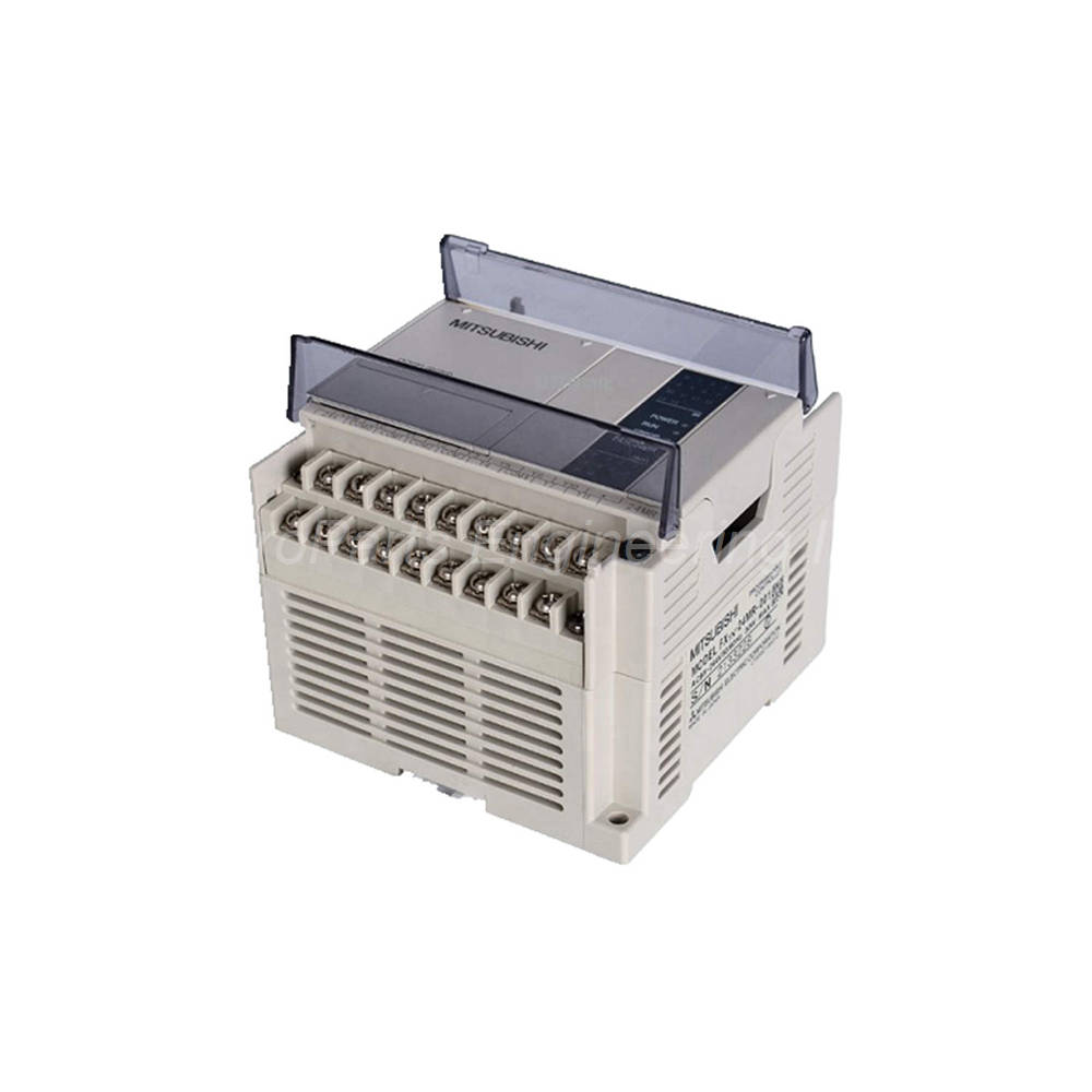
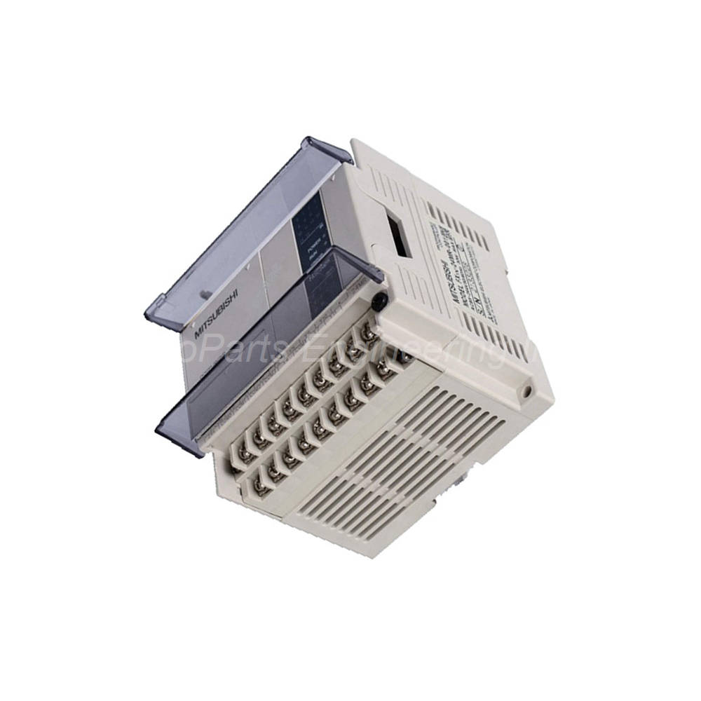
Mitsubishi Electric FX1N-24MT-001 Programmable Logic Controller
Product Overview
The FX1N-24MT-001 is a reliable main unit from the FX1N Series. This programmable controller provides 24 total I/O points for small to medium automation tasks. The unit includes 14 digital inputs and 10 transistor outputs. Engineers often choose this model for its balanced I/O count and compact size. Consequently, the FX1N-24MT-001 works well for conveyor control and packaging machines. Additionally, this PLC supports interrupt instructions for time-critical operations.
Control System and Memory
The arithmetic system uses a stored program repeat operation method. Therefore, the FX1N-24MT-001 executes logic predictably and repeatedly. The I/O control method employs batch processing with an END instruction refresh. Programming languages include relay symbol systems and step ladder with SFC representation.
The program memory holds up to 8000 steps maximum. Built-in memory consists of 8000 steps of EEPROM storage. Notably, this EEPROM requires no backup battery for program retention. For additional memory, you can install the FX1N-EEPROM-8L memory cassette. The RUN during write function lets you change programs while the sequencer runs. As a result, you experience minimal downtime during debugging. A password protection feature uses a keyword function for security.
Real-Time Clock Details
The FX1N-24MT-001 includes a built-in real-time clock. This clock covers dates from 1980 to 2079 with leap year correction. The month deviation measures only ±45 seconds at 25°C. However, you should note the backup mechanism carefully. A large-capacity capacitor backs up the clock after 30 minutes of charging. This capacitor holds the current time for 10 days without external power. For example, if you power down the system for a week, the clock remains accurate. For longer shutdowns, consider installing an optional battery.
Processing Speed and Instruction Set
The FX1N-24MT-001 processes basic instructions in 0.55 to 0.70 microseconds. Application instructions require 3.7 to 100 microseconds per operation. Therefore, this PLC handles high-speed logic with ease. The instruction set includes 27 basic sequence instructions and 2 step ladder instructions. Additionally, you get 89 application instructions for advanced functions.
Device Memory Organization
The input relays range from X000 to X177, providing 128 points of octal addressing. Output relays range from Y000 to Y177, also offering 128 points. Consequently, you can expand the system significantly. Auxiliary relays split into several categories. General use relays M0 to M383 offer 384 non-keep points. EEPROM keep relays M384 to M511 provide 128 points for critical flags. Capacitor keep relays M512 to M1535 deliver 1024 points of retentive storage.
Special auxiliary relays M8000 to M8255 give you 256 system-defined points. State relays S0 to S9 serve as initial state with EEPROM keep. Moreover, S10 to S127 offer 118 points of EEPROM keep storage. S128 to S999 deliver 872 points of capacitor keep storage.
Timer and Counter Functions
The FX1N-24MT-001 includes various timer types for flexible control. For instance, 100ms timers T0 to T199 provide 200 points with 0.1 to 3276.7 second ranges. 10ms timers T200 to T245 offer 46 points for more precise timing. Additionally, 1ms integration timers T246 to T249 give you 4 points with capacitor keep. 100ms integration timers T250 to T255 supply 6 points also with capacitor keep.
Counter options are equally diverse. Specifically, 16-bit up counters C0 to C15 provide 16 points for general counting. C16 to C31 offer 16 points of EEPROM keep up counting. C32 to C199 deliver 168 points of capacitor keep up counting. Furthermore, 32-bit up/down counters C200 to C219 give you 20 bidirectional points. C220 to C234 provide 15 points of capacitor keep bidirectional counting.
High-Speed Counter Capabilities
The FX1N-24MT-001 excels in high-speed counting applications. For example, 1-phase 1-count inputs on C235 and C236 operate at 60 kHz maximum. C237 through C245 run at 10 kHz for less demanding tasks. Similarly, 1-phase 2-count input on C246 reaches 60 kHz peak performance. C247 through C250 operate at 10 kHz for standard applications.
For quadrature encoder signals, 2-phase 2-count input on C251 achieves 30 kHz. Moreover, C252 through C255 provide 5 kHz for basic motion control. The total frequency sum treated by the sequencer reaches 60 kHz maximum. Consequently, the FX1N-24MT-001 handles demanding counting tasks reliably.
Data Register Structure
Data registers provide analog value and data storage. Specifically, 16-bit general registers D0 to D127 offer 128 points. EEPROM keep registers D128 to D255 supply another 128 points. Capacitor keep registers D256 to D7999 deliver an impressive 7744 points of storage. Additionally, file registers D1000 to D7999 provide up to 7000 points of EEPROM space. Special registers D8000 to D8255 give you 256 system monitoring points. Finally, index registers V0 to V7 and Z0 to Z7 offer 16 points for indirect addressing.
Built-in Positioning and Pulse Output
The FX1N-24MT-001 includes powerful positioning functions. Notably, you get independent 2-axis control with this unit. The maximum output frequency reaches 100 kHz for high-speed positioning. Pulse output instructions include PLSY (pulse output) and PLSR (accel/decel). Therefore, you can control stepper motors and servo drives directly.
Positioning instructions cover all common motion tasks. For example, ABS reads absolute current values from drives. ZRN performs homing without a DOG search function. PLSV provides variable-speed pulse output for smooth acceleration. Additionally, DRVI handles relative positioning moves. DRVA executes absolute positioning to exact coordinates. The output format uses pulse train plus direction signal.
Power Supply Specifications
The FX1N-24MT-001 accepts a wide DC power range. Rated voltage spans DC12 to 24V for flexibility. The allowable range extends from DC10.2 to 28.8V. Consequently, this PLC tolerates voltage fluctuations well. The unit continues operation through momentary failures under 5ms. A 125V 3.15A power fuse protects the internal circuits. Inrush current reaches 25A maximum at 1ms for DC24V. Power consumption measures 15W, including input current draw.
Input Specifications
The FX1N-24MT-001 provides 14 input points on a removable terminal block. M3 screws secure all wiring connections. Specifically, this unit uses sink input format for compatibility. Input signal voltage requires DC24V ±10% for proper operation. Input impedance measures 3.3kΩ for X000 to X007. Additionally, X010 and above use 4.3kΩ impedance. Input current draws 7mA at DC24V for X000 to X007. X010 and above draw 5mA at the same voltage.
ON sensitivity requires more than 4.5mA for X000 to X007. Similarly, X010 and above need more than 3.5mA to turn ON. OFF sensitivity requires 1.5mA or less for reliable OFF state. Input response time typically measures 10ms. However, X000 to X007 include a digital filter. You can adjust this filter from 0 to 15ms in 1ms steps via D8020. Consequently, you match response time to your specific sensor needs. Photocouplers provide input circuit isolation. Finally, an LED lights when each input turns ON.
Output Specifications
The FX1N-24MT-001 provides 10 transistor output points. These outputs use sink type format for standard applications. External power requires DC5 to 30V for proper operation. Therefore, you can connect various loads safely. Resistance load capacity reaches 0.5A per output point. Each common COM terminal handles 0.8A maximum. Inductive load capacity measures 12W at DC24V.
Open circuit leakage current stays below 0.1mA at DC30V. ON voltage remains at 1.5V maximum for low heat generation. Notably, Y000 and Y001 offer very fast response. Their OFF to ON response time measures only 5 microseconds. Their ON to OFF response time also measures 5 microseconds. Additionally, Y002 and above provide 0.2ms or less response time. Photocouplers isolate output circuits from the logic side. Finally, an LED lights when the photocoupler drives each output.
Environmental and Physical Specifications
The FX1N-24MT-001 operates reliably in harsh environments. Operating temperature ranges from 0 to 55°C. Storage temperature extends from -20 to 70°C. Additionally, relative humidity stays between 35 and 85% RH without condensation.
Vibration resistance varies by mounting method. For instance, DIN rail mounting tolerates 10-57Hz at 0.035mm amplitude. Direct mounting tolerates 10-57Hz at 0.075mm amplitude. Furthermore, higher frequencies up to 150Hz use acceleration values. DIN rail mounting uses 4.9 m/s² for 57-150Hz. Direct mounting uses 9.8 m/s² for the same frequency range.
Shock resistance reaches 147 m/s² for 11ms duration. Consequently, the FX1N-24MT-001 survives industrial impacts. Noise immunity handles 1000Vp-p with 1μs pulse width. Dielectric withstand tests at AC500V for 1 minute. Insulation resistance measures 5MΩ minimum at DC500V. Finally, grounding requires Class D with 100Ω or less resistance. Do not share ground with high-voltage systems.
Installation Guide
Follow these steps to install the FX1N-24MT-001 correctly.
-
Mount the Unit: Install on a DIN rail or use M4 screws directly.
-
Check Spacing: Keep 50 mm minimum clearance above and below.
-
Connect Power: Apply DC12-24V to the dedicated power terminals.
-
Ground Properly: Use Class D grounding at 100Ω or less separately.
-
Wire Inputs: Connect sensors to X000 through X015 terminals.
-
Wire Outputs: Connect loads to Y000 through Y007 terminals.
-
Prepare Software: Use GX Developer or GX Works2 for programming.
-
Initialize Memory: Reset capacitor keep devices for first-time use.
Important: Always turn off power before wiring the FX1N-24MT-001. Additionally, initialize capacitor keep areas after long storage periods. This ensures reliable operation of retentive memory.
Package Contents
-
One FX1N-24MT-001 main unit
-
One user manual (hardware guide)
-
One set of terminal labels
-
One DIN rail mounting clip kit
Frequently Asked Questions (FAQ)
1. Can the FX1N-24MT-001 use FX1N series expansion modules?
Yes, the FX1N-24MT-001 supports all FX1N expansion modules. You can add I/O, analog, and communication modules easily. However, the total I/O must not exceed 128 points.
2. How long does capacitor keep data last without external power?
The FX1N-24MT-001 holds capacitor keep data for 10 days maximum. The large capacitor needs 30 minutes of charging to reach full capacity. Therefore, install an optional battery for longer power-off retention.
3. What is the maximum pulse output frequency for positioning tasks?
The FX1N-24MT-001 supports up to 100 kHz pulse output frequency. This applies specifically to Y000 and Y001 outputs. Use PLSY or PLSR instructions for pulse generation.
4. How do I enable password protection on this PLC unit?
Use the keyword function within GX Developer software. First, go to Parameter → PLC Parameter → Keyword menu. Then, set an 8-character password for the FX1N-24MT-001. The password prevents unauthorized program read or write access.
5. Does the FX1N-24MT-001 include a real-time clock function?
Yes, the FX1N-24MT-001 has a built-in real-time clock. It tracks years from 1980 to 2079 with automatic leap year correction. Consequently, you can timestamp events accurately. The clock runs on a large capacitor backup for 10 days without power.

 Customer Reviews