
Woodward 5464-334 Isolated Analog Input Module 8 Channel 4-20mA
Introduction:
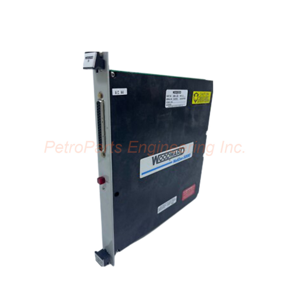
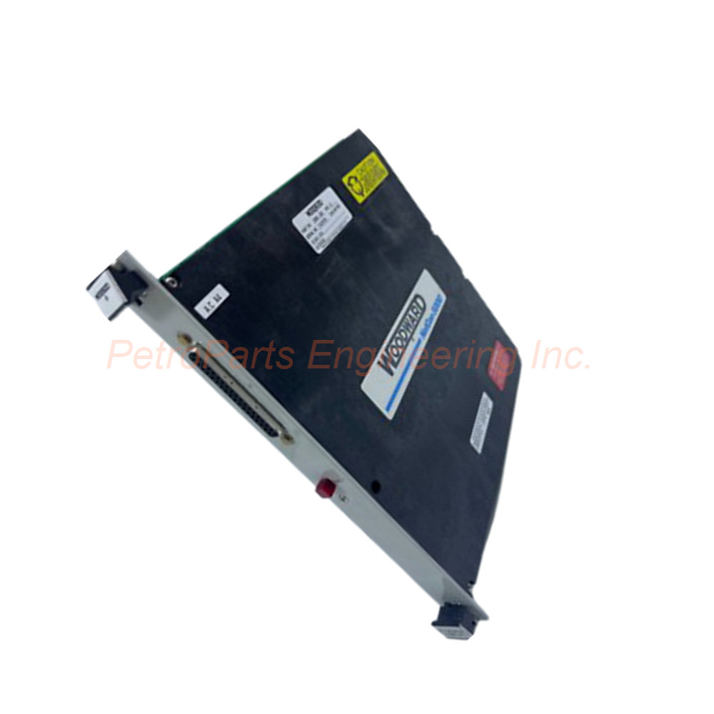
The Woodward 5464-334 is an isolated 4-20mA analog input module with 8 channels. It features 3000 VDC isolation protection and an onboard microcontroller. This 5400 series module suits turbine control systems and industrial automation.
 Customer Reviews
UBEST Automation – Trusted Global Automation Parts Supplier
We offer a wide range of in-stock industrial automation spare parts. All products come with a 12-month warranty and a 30-day refund for quality issues.
Product Attributes:
Notice: For real-time prices and inventory, please click the button below to contact us.
Product Overview of the Woodward 5464-334 Analog Input Module
The Woodward 5464-334 is part of the 5400 Series for turbine control systems. This module accepts analog signals within the 4 to 20 milliamp range. Each of the 8 channels is fully isolated from the others. Electrical separation between channels prevents interference and ensures accurate measurements.
The Smart I/O module incorporates its own onboard microcontroller. Upon initialization, the microcontroller runs power-on self tests automatically. The LED deactivates once tests complete and the CPU initializes the module. If an I/O fault occurs, the LED illuminates to signal the problem.
The Woodward 5464-334 uses an initialization and key broadcast system. Every I/O module manages its own rate group scheduling independently. This design requires minimal CPU involvement for I/O handling. The module includes on-card online fault detection capabilities.
Technical Specifications of the 5464-334
Part Number: 5464-334
Manufacturer: Woodward
Product Type: Isolated 4-20mA Analog Input Module
Number of Channels: 8
Input Signal Range: 4 to 20 mA
Input Voltage: 24 Vdc
Maximum Operating Current: 12 V
Isolation Protection: 3000 VDC
Power Supply Range: 10 to 60 VDC
Operating Temperature: -25°C to +70°C
Dimensions: 30 cm x 20 cm x 25 cm
Weight: 0.8 kg
Country of Origin: United States (USA)
The Woodward 5464-334 operates on a 10 to 60 VDC power supply range. The isolation protection of 3000 VDC safeguards sensitive control circuits. The operating temperature range suits harsh industrial turbine environments. Each channel maintains independent isolation from all other channels.
Onboard Microcontroller and Self Diagnostics
The 5464-334 includes an onboard microcontroller for intelligent operation. Each input channel has its own precision voltage reference. Once per minute during idle periods, the microcontroller reads this reference. The module reads references when inputs are not being actively scanned.
The microcontroller uses voltage reference data for fault detection. It also performs automatic temperature compensation and calibration. The system has predefined thresholds for expected reference readings. If a reading falls outside these limits, a fault is identified.
The fault may be in the input channel, the A/D converter, or the voltage reference. The microcontroller signals a fault condition for that specific channel. The CPU then executes actions defined by the application engineer. This automatic fault detection improves system reliability.
Accuracy and Temperature Compensation
The Woodward 5464-334 maintains high accuracy across temperature changes. Automatic temperature compensation adjusts for thermal drift in measurements. The precision voltage reference provides a stable comparison point. The microcontroller reads this reference regularly for calibration.
Each channel's accuracy benefits from individual reference voltages. This design prevents a single reference failure from affecting multiple channels. Temperature compensation happens automatically without user intervention. The module continues to provide accurate readings across the -25°C to +70°C range.
The onboard calibration eliminates manual trim potentiometers. Digital calibration values are stored in non-volatile memory. These values persist through power cycles and module resets. The Woodward 5464-334 delivers consistent performance over time.
Installation Guide for the 5464-334
Follow these steps to install the Woodward 5464-334 correctly.
Power down the control system before handling the module.
Insert the module into an available slot in the rack.
Secure the module with the retaining screws or latches.
Connect the 10 to 60 VDC power supply to the terminals.
Verify the supply voltage stays within the specified range.
Connect each 4-20mA field device to an input channel.
Observe correct polarity for each analog input connection.
Use shielded twisted pair wiring for all analog signals.
Ground the shield only at the module end of each cable.
Power up the system and verify the LED behavior.
The visible fuse is accessible through a cutout in the plastic cover. Replace a blown fuse with an identical type and size only. Do not exceed the maximum operating current specifications. Keep wiring away from high voltage power cables.
Package Contents for Woodward 5464-334
1 x Woodward 5464-334 isolated analog input module
1 x Set of removable terminal blocks for wiring
1 x Replacement fuse (visible type, pre-installed)
1 x Installation and configuration manual
Frequently Asked Questions (FAQ)
1. What is the purpose of 3000 VDC isolation on the 5464-334?
The 3000 VDC isolation protects the control system from field wiring faults. It prevents high voltages from damaging the CPU or other modules. Each channel is isolated from other channels and from ground.
2. How does the automatic temperature compensation work on this module?
The Woodward 5464-334 reads a precision voltage reference once per minute. The onboard microcontroller uses this data to adjust for temperature drift. This happens automatically without any user action required.
3. What does the LED indicate during normal operation?
The LED deactivates after successful power-on self tests complete. This indicates the module is initialized and working properly. If the LED illuminates, an I/O fault has been detected on the module.
4. Can I use this module with 0-20mA sensors instead of 4-20mA?
The 5464-334 is designed specifically for 4-20mA input signals. The fault detection thresholds expect 4mA as the minimum valid signal. Using 0-20mA sensors may trigger false underrange fault indications.
5. What should I do if a channel fails the self diagnostic test?
Check the visible fuse accessible through the module's plastic cover. Replace the fuse if it appears blown. If the fuse is intact, the channel may require module replacement or factory repair.