
Triconex 3502E TMR Digital Input Module | 48V 32 Points
Introduction:
The Triconex 3502E delivers 32 TMR digital inputs for 48V systems. It handles 35-95V AC/DC with stuck-on self-test and hot-spare capability.
![]() Customer Reviews
Customer Reviews
UBEST Automation – Trusted Global Automation Parts Supplier
We offer a wide range of in-stock industrial automation spare parts. All products come with a 12-month warranty and a 30-day refund for quality issues.
Product Attributes:
Notice: For real-time prices and inventory, please click the button below to contact us.
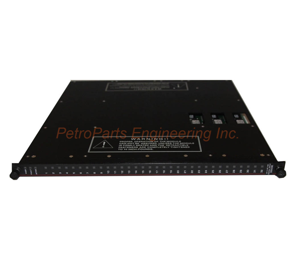
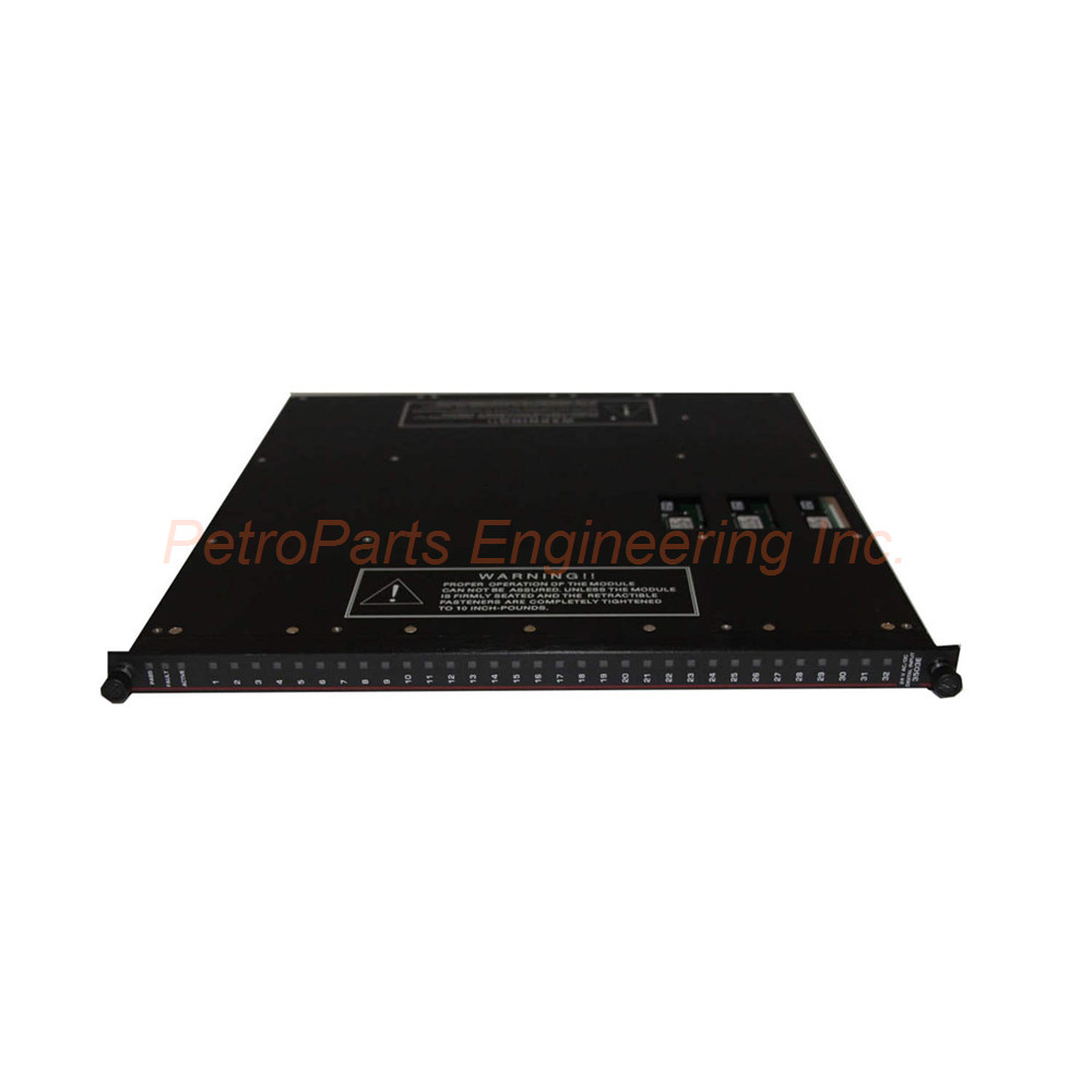
Triconex 3502E TMR Digital Input Module
The Triconex 3502E is a Triple Modular Redundant (TMR) digital input module. This unit provides 32 input points for high-voltage safety applications. Each group of 8 points shares a common return path. The Triconex 3502E operates at a nominal voltage of 48 VAC/VDC. Engineers use this module in power generation and heavy industrial safety systems.
Stuck-ON Self-Test Feature Explained
The Triconex 3502E can self-test to detect stuck-ON conditions. This test identifies when circuitry cannot tell whether a point reached the OFF state. Most safety systems use a de-energize-to-trip architecture in their design. Therefore, detecting OFF points becomes an important safety feature for your facility.
How does the stuck-ON test work in detail? A switch within the input circuitry closes during testing. This action allows a zero input (OFF) to be read by the optical isolation circuitry. While the test runs, the I/O communication processor freezes the last data reading. Your system continues operating with known good data during this brief test period. This frozen state prevents false trip events during self-testing.
Hot-Spare Capability and External Requirements
All TMR digital input modules support hot-spare capability fully. You can install a backup module without powering down the Tricon chassis. Each Triconex 3502E requires a separate external termination panel (ETP). A cable interface connects the ETP to the Tricon controller backplane. This design keeps field wiring away from the main chassis for easier maintenance.
Mechanical Keying for Installation Safety
The module includes mechanical keying features for safe installation. This keying prevents improper insertion into a configured chassis. You cannot install the Triconex 3502E into the wrong slot accidentally. This physical protection reduces configuration errors during routine maintenance.
Core Architecture and Module Type
The Triconex 3502E features TMR architecture with integrated self-test functionality. Three isolated input channels independently process all data entering the module. Each channel conditions signals separately from the others. The module also provides optical isolation between the field and the Tricon controller. This triplicated design guarantees safety and maximum system availability.
Input Voltage Range and Frequency
Regarding voltage requirements, the Triconex 3502E accepts a range from 35 to 95 VAC/VDC. The maximum allowable voltage reaches 95 VAC/VDC without damaging the unit. For frequency, this module works with DC signals or AC from 47 to 63 Hz. This wide range accommodates various industrial power sources. Nominal input impedance measures greater than 2.9 KΩ per channel.
Switching Thresholds and Hysteresis
For switching levels, the OFF to ON transition occurs below 32 VAC/VDC. Conversely, the ON to OFF transition happens above 11 VAC/VDC. The nominal turn-on current sits between 6 mA and 9 mA per point. Typical hysteresis measures 7 VAC/VDC for stable switching behavior. This hysteresis prevents chattering when input signals fluctuate near threshold levels.
Input Delay Timing Specifications
The Triconex 3502E delivers predictable response delays for safety logic execution. The OFF to ON transition takes less than 8 ms to complete. Meanwhile, the ON to OFF transition requires less than 15 ms. These fast response times suit time-critical safety applications perfectly. Your control loop experiences minimal latency from high-voltage field input devices.
Point Isolation and Power Load
The module provides 1,500 VDC of point-to-point isolation protection. This high isolation guards against voltage spikes and ground loop currents. Each ON point consumes 1.0 watts of field power typically. At maximum field voltage, each active point uses 3.2 watts. Multiply these values across 32 points for total power calculations. Use the worst-case figure of 3.2 watts for conservative system design.
Diagnostic Indicators for Status Monitoring
The Triconex 3502E includes comprehensive diagnostic LEDs for easy troubleshooting. Each of the 32 points features an individual Input Status indicator. For module health, you will see PASS, FAULT, and ACTIVE status lights. A Stuck Test ON indicator shows when self-testing is active. The module carries a Dark Red color code for visual identification in the chassis.
Step-by-Step Installation Guide
Follow these steps to install your Triconex 3502E correctly.
Step 1: Verify Chassis Compatibility
Ensure your Tricon chassis has an available I/O slot first. Check that the backplane firmware supports TMR digital input modules. Also, confirm the slot configuration matches your engineering drawings.
Step 2: Install the External Termination Panel
Mount the ETP in a suitable location near your field devices. Use the recommended cable to connect the ETP to the Tricon backplane. Tighten all connections to specified torque values shown in the manual.
Step 3: Set the Mechanical Keying
Adjust the keying pins on the module and chassis slot carefully. Match the keying pattern to your engineering documentation. This step prevents future installation errors by maintenance staff.
Step 4: Insert the Module
Slide the Triconex 3502E firmly into the designated chassis slot. Press until the top and bottom latches click into place securely. Verify the module sits flush with adjacent modules after installation.
Step 5: Connect Field Wiring
Wire your field devices to the ETP terminal blocks correctly. Connect each input signal to the proper point number. Group returns according to the 8-point commoning scheme shown in the manual.
Step 6: Apply Power and Test
Power up the Tricon chassis and observe the diagnostic LEDs. The PASS indicator should light up after initialization completes. Run a stuck-on self-test to verify proper operation of your Triconex 3502E.
Complete Package Contents
Your Triconex 3502E shipment includes the following items:
Triconex 3502E TMR Digital Input Module (1 unit)
Module keying pins and installation tool
Product documentation and configuration guide
Dust cover for unused chassis slots
Note: Shipping partners include FedEx, UPS, and DHL.
Frequently Asked Questions (FAQ)
Q1: What is the nominal voltage rating for the Triconex 3502E?
The Triconex 3502E has a nominal voltage rating of 48 VAC/VDC. It accepts a range from 35 to 95 VAC/VDC for flexible application. This makes it suitable for 48V industrial control systems.
Q2: How does the Triconex 3502E differ from the 3503E and 3505E?
The Triconex 3502E handles higher voltages up to 95V. The 3503E works with 24V systems, while the 3505E handles 24V DC only. Each model serves different field voltage requirements.
Q3: Does the Triconex 3502E support hot-swapping during operation?
Yes, this module supports hot-spare capability fully. You can replace a failed module without powering down the Tricon chassis. However, ensure the backup module has identical configuration settings.
Q4: What external components does the Triconex 3502E require?
The Triconex 3502E needs a separate external termination panel (ETP). You also need a cable interface to connect the ETP to the backplane. The ETP provides terminal blocks for all field wiring connections.
Q5: What happens to input data during a stuck-on self-test?
During the stuck-on test, the I/O processor freezes the last data reading. This frozen state prevents false trip events during testing. Normal input scanning resumes immediately after the test completes.
Welcome to learn about our business. We are a leading global provider of automation equipment and will provide you with complete and cost-effective product solutions. You are welcome to choose us, and our services will make you a long-term partner like our other customers.
Now please let us know your needs and suggestions.
About Ubest
Ubest Automation is a leading global provider of automation products, with deep partnerships with major automation manufacturers to provide customers with customized business solutions, cost-effective products, and comprehensive services.
Product Center
Contact Us
Phone:+86 180 3000 5825
Address:Room 7A, No. 59 Hubin North Road, Siming District Xiamen City China
Email: sales@ubestplc.com
Contact: Klaus
Industry Links
© 2026, Ubest Automation Limited All Rights Reserved. sitemap