
SICK LMS500-21000 LiDAR Sensor | 80m Range 190° Scan
Introduction:
The SICK LMS500-21000 offers 80m scanning range with 190° aperture. Features 75Hz scan rate, ±12mm accuracy, and IP65 protection for indoor use.
 Customer Reviews
UBEST Automation – Trusted Global Automation Parts Supplier
We offer a wide range of in-stock industrial automation spare parts. All products come with a 12-month warranty and a 30-day refund for quality issues.
Product Attributes:
Notice: For real-time prices and inventory, please click the button below to contact us.
SICK LMS500-21000 2D LiDAR Sensor
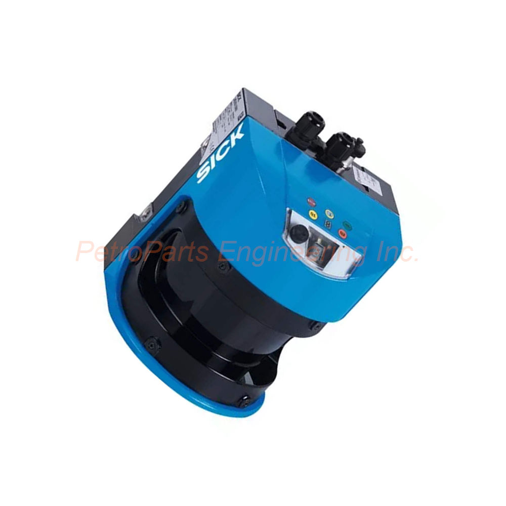
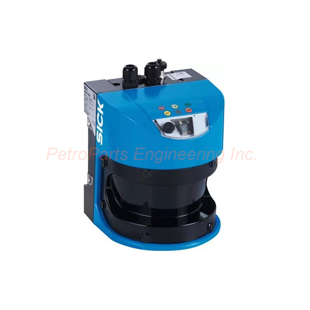
The SICK LMS500-21000 is a 2D LiDAR sensor from the LMS500 series. This unit carries the Lite variant designation for indoor applications. Specifically, the LMS500-21000 offers high resolution power for detailed environment scanning. Infrared light at 905 nm (± 10 nm) serves as the invisible light source. For area monitoring and object detection, engineers trust this sensor. Profile measurement applications also benefit from its precision.
Laser Safety and Aperture Angle
Regarding laser safety, the class reaches Class 1 per EN/IEC 60825-1:2014 standards. Compliance with EN 60825-1:2014+A11:2021 ensures complete eye safety. Consequently, no special laser safety equipment is needed during operation. The horizontal aperture angle measures 190° for wide area coverage. Due to this wide angle, the sensor suits large indoor spaces. Warehouses and factories benefit from this extensive field of view.
Scanning Frequency and Angular Resolution
Four configurable scanning frequencies provide application flexibility. Available frequencies include 25 Hz, 35 Hz, 50 Hz, and 75 Hz. Higher scan rates capture faster moving objects with better detail. On the other hand, lower scan rates provide more processing time per measurement. Similarly, the horizontal angular resolution offers three configuration options. Depending on your detail requirements, choose 0.25°, 0.5°, or 1.0°. Finer resolution detects smaller objects, yet it increases data output volume.
Scan Field Flatness and Conical Error
Turning to scan field geometry, the flatness combined measures ± 0.72° for consistent scanning. The typical conical error sits at 0.11° ± 0.1° at 1 sigma value. Because this error remains low, accurate positioning occurs across the entire scan field. The typical tilt measures 0.15° ± 0.08° at 1 sigma value. Even with minor mounting angle variations, reliable data is provided.
Working Range and Scanning Capabilities
Versatile coverage comes from a working range of 0.2 m to 80 m. At 10% remission factor, however, the scanning range reaches 26 m reliably. Darker objects with lower reflectivity will produce shorter effective ranges. Precise distance data comes from ± 12 mm measurement accuracy. Furthermore, the amount of evaluated echoes reaches 2 for improved reliability. Rejecting spurious reflections from dust or rain is possible with multiple echoes.
Spot Size and Beam Divergence
Regarding the laser beam, divergence measures 4.7 mrad for the emitted pulse. A 13.5 mm spot size appears at the viewing window. At 26 meters distance, however, the spot expands to 136 mm. At 40 meters distance, the spot size reaches 202 mm. Consequently, larger spots may average over small object features at long range.
Electrical Specifications and Power Requirements
For connections, the sensor includes 1 x M12 round connector for Ethernet. Additionally, 1 x system plug with screw terminal block provides power and I/O connections. Two cable glands come with this system plug for secure cable entry. The supply voltage requires 24 V DC with ± 20 % tolerance. Therefore, the acceptable range spans from 19.2 V to 28.8 V DC. Normal operation consumes 22 W of power.
Mechanical Construction and Materials
AlSi12 aluminum alloy forms the housing for strength and heat dissipation. Easy identification comes from the light blue (RAL 5012) housing color. For optical clarity, the window uses polycarbonate with scratch-resistant coating. Per EN 60529, Section 14.2.7, the enclosure rating reaches IP65. Consequently, the sensor resists dust ingress and low-pressure water jets. Safety extra low voltage operation is ensured by Protection Class III per IEC 61140:2016-11.
Dimensions and Weight
Moving to physical size, the dimensions (L x W x H) measure 160 mm x 155 mm x 185 mm. Stable installation comes from a 3.7 kg weight. For this reason, use sturdy mounting brackets to support this weight securely. Cold environment operation is supported by self-heating.
Reliability and Performance Parameters
Regarding reliability, the MTBF exceeds 100 years for exceptional performance. Similarly, the MTTFD exceeds 100 years for safety-related calculations. Fast detection of moving objects comes from a ≥ 13 ms response time. Due to the active LiDAR principle, the detectable object shape is almost any.
Measurement Errors and Accuracy
Distance from the sensor affects the systematic error. From 1 m to 10 m, the error equals ± 25 mm. From 10 m to 20 m, however, the error expands to ± 35 mm. Distance also affects the statistical error accordingly. A 7 mm error appears from 1 m to 10 m. From 10 m to 20 m, the error equals 9 mm.
Integrated Application and Field Evaluation
Real-time zone monitoring comes from the field evaluation integrated application. Your control system receives continuous measurement data output. Complex zone definitions are supported by 4 field sets. For multiple independent monitoring tasks, 4 simultaneous evaluation cases are available. As a result, one sensor can protect several areas simultaneously.
Filter Options for Reliable Detection
Several filters improve detection reliability in challenging conditions. Spurious reflections from unwanted objects are rejected by the echo filter. Similarly, the fog filter improves performance in humid or misty environments. Small dust or debris particles are ignored by the particle filter effectively. Meanwhile, noisy measurements are smoothed by the average filter for stable output. Finally, interference from bright light sources is handled by the glare filter.
Communication Interfaces and Protocols
For networking, the LMS500-21000 includes Ethernet with TCP/IP and UDP/IP protocols. Host and AUX functions plus NTP time synchronization are supported. Fast data transfer comes from a 10/100 MBit/s transmission rate. Additionally, serial communication supports RS-232 and RS-422 standards. Host and AUX functions are also supported by this interface. From 9.6 kBaud to 500 kBaud, the data transmission rate ranges. For service access, USB with Mini-USB connector is available.
Digital I/O and Status Indicators
External trigger or synchronization uses 2 digital inputs. Alarm or status signaling uses 3 digital outputs. For quick status checking, 5 LEDs serve as optical indicators. Additionally, error codes and configuration information appear on a 7-segment display.
Ambient Conditions and Object Remission
From 2% to > 1,000% including reflectors, the object remission range spans. Very dark objects (2% remission) produce the shortest detection ranges. In contrast, reflectors (>1,000% remission) produce the longest detection ranges. From 0 °C to +50 °C, the ambient operating temperature ranges. For warehouse conditions, storage temperature spans from –40 °C to +70 °C. Furthermore, 70,000 lx ambient light immunity ensures reliable operation in bright conditions.
Environmental Compliance and Immunity
Regarding EMC, emitted radiation complies with IEC 61000-6-3:2020. For industrial environments, EN IEC 61000-6-3:2007+A1:2011 is also met. For immunity, compliance meets IEC 61000-6-2:2016 and EN IEC 61000-6-2:2019. Vibration resistance follows sine test at 10 Hz to 150 Hz. From 0.35 mm to 5 g, amplitude ranges for 20 cycles. For shock, resistance withstands 15 g at 11 ms for 6 single shocks per axis. Additionally, 10 g at 16 ms for 1,000 continuous shocks per axis is tolerated. Per DIN EN 50102:09-1997, impact resistance meets IK05, IK06, and IK07.
Important Usage Note
Please note that the SICK LMS500-21000 does not constitute a safety component. Relevant legislation for machine safety applications is not met. Therefore, for safety-critical functions, select a certified safety laser scanner instead. This sensor serves monitoring and measurement applications only.
Step-by-Step Installation Guide
Follow these steps to install your SICK LMS500-21000 correctly.
Step 1: Select the Mounting Location
First, choose a location with a clear 190° view of the monitoring area. Indoor mounting within 0°C to +50°C is required. Strong light sources that may cause glare should be avoided. Then, ensure the mounting surface can support the 3.7 kg weight.
Step 2: Mount the Sensor Securely
Next, attach the LMS500-21000 using M6 mounting bolts. Use the mounting holes on the light blue AlSi12 housing. Tighten bolts to the specified torque value without exception. For stable operation in cooler environments, self-heating is included.
Step 3: Connect Power and Ethernet
After mounting, wire the 24 V DC power supply to the system plug. Secure cable entry uses the screw terminal block with cable glands. Connect the M12 Ethernet connector to your network switch. Then, verify all connections are tight before applying power.
Step 4: Configure the Scanning Parameters
Now, access the sensor configuration software via Ethernet. Select the scanning frequency between 25 Hz and 75 Hz for your application. Choose the angular resolution between 0.25°, 0.5°, or 1.0° as needed. Then, configure the echo and particle filters for your specific environment.
Step 5: Define the Protection Fields
Using the software, draw the 4 field sets for zone monitoring. For each field, set the working range between 0.2 m and 80 m. For complex monitoring, define up to 4 simultaneous evaluation cases. Then, test each field set thoroughly with a moving object.
Step 6: Test the Detection Functions
Apply power to the LMS500-21000 and observe the LED indicators. Move an object through each monitoring zone to verify detection. Check whether the digital outputs activate at the correct distances. Finally, document all configuration settings for future reference.
Complete Package Contents
Your SICK LMS500-21000 shipment includes the following items:
SICK LMS500-21000 2D LiDAR Sensor (1 unit)
System plug with screw terminal block and 2 cable glands
M12 Ethernet connector cap
Product documentation and quick start guide
Configuration software download card
Note: Shipping partners include FedEx, UPS, and DHL.
Frequently Asked Questions (FAQ)
Q1: What is the maximum scanning range of the LMS500-21000?
Under ideal conditions, the working range reaches 80 meters for the LMS500-21000. At 10% target remission, however, the reliable scanning range is 26 meters. Very dark objects at 2% remission will produce shorter detection distances.
Q2: Is the LMS500-21000 a safety-rated device?
No, the SICK LMS500-21000 is not a safety component for machine safety. Relevant safety legislation requirements are not met whatsoever. For safety applications, use a certified safety laser scanner instead.
Q3: What scanning frequencies does this sensor support?
Four configurable scanning frequencies are supported by the LMS500-21000. These include 25 Hz, 35 Hz, 50 Hz, and 75 Hz for application flexibility. Consequently, higher frequencies capture faster moving objects with better detail.
Q4: Does the LMS500-21000 work outdoors?
Indoor applications only are supported by the LMS500-21000. Specifically, the operating temperature range is 0°C to +50°C for reliable performance. For outdoor use, select a model with broader temperature and weather protection.
Q5: What communication interfaces are available on this sensor?
Ethernet (TCP/IP, UDP/IP) at 10/100 MBit/s is included on the SICK LMS500-21000. Additionally, serial RS-232 and RS-422 at 9.6 to 500 kBaud are provided. For configuration access, a Mini-USB service port is also available.
Welcome to learn about our business. We are a leading global provider of automation equipment and will provide you with complete and cost-effective product solutions. You are welcome to choose us, and our services will make you a long-term partner like our other customers.
Now please let us know your needs and suggestions.
About Ubest
Ubest Automation is a leading global provider of automation products, with deep partnerships with major automation manufacturers to provide customers with customized business solutions, cost-effective products, and comprehensive services.
Product Center
Contact Us
Phone:+86 180 3000 5825
Address:Room 7A, No. 59 Hubin North Road, Siming District Xiamen City China
Email: [email protected]
Contact: Klaus
Industry Links
© 2026, Ubest Automation Limited All Rights Reserved. sitemap