
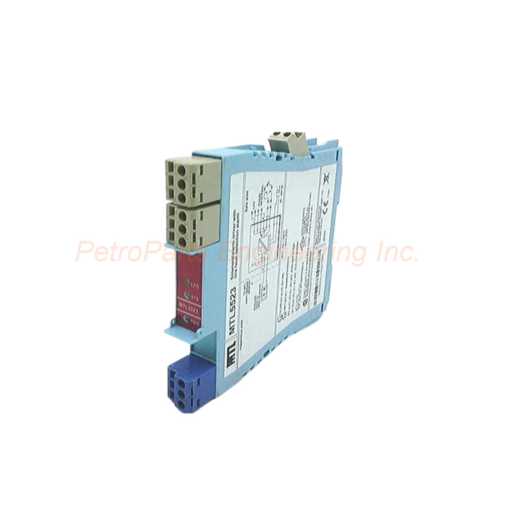
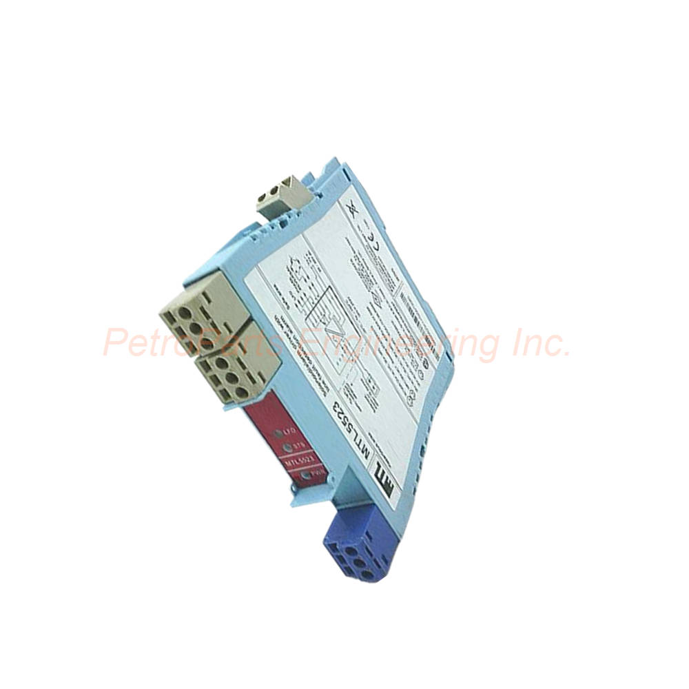
MTL5523 MTL Intrinsic Safety Solenoid Driver Interface One Channel
Introduction:
The MTL5523 is a single-channel intrinsic safety interface for hazardous areas. It controls on/off devices like solenoids from a safe area using a volt-free contact or logic signal. This module includes Line Fault Detection (LFD) for open or short circuits in field wiring. Consequently, it is ideal for Zone 0 and Division 1 hazardous locations.
 Customer Reviews
UBEST Automation – Trusted Global Automation Parts Supplier
We offer a wide range of in-stock industrial automation spare parts. All products come with a 12-month warranty and a 30-day refund for quality issues.
Product Attributes:
Notice: For real-time prices and inventory, please click the button below to contact us.
Product Overview: MTL5523
Designed for controlling hazardous area on/off devices, the MTL5523 is a single-channel solenoid/alert driver interface. A volt-free contact or logic signal in the safe area controls the unit. It then drives loads such as solenoids located in Zone 0, IIC, T4–6 hazardous areas. For North American installations, the unit supports Division 1, Group A hazardous locations. Consequently, this device is ideal for remote valve actuation and alarm annunciation in intrinsically safe systems.
Technical Specifications
The MTL5523 provides a hazardous-area output with a minimum voltage of 13.6V at 48mA. Maximum output voltage reaches 24V from a 180Ω source. The maximum off-state output voltage is 4V from 180Ω, ensuring reliable turn-off. Current limiting engages at 48mA minimum to protect the field device. Output ripple measures less than 0.5% of maximum output peak-to-peak.
Number of Channels: One
Minimum Output Voltage: 13.6V at 48mA
Maximum Output Voltage: 24V from 180Ω
Off-State Output Voltage: 4V maximum from 180Ω
Current Limit: 48mA minimum
Output Ripple: <0.5% of maximum output, peak to peak
The MTL5523 maximum current consumption is 100mA at 24V DC. Power dissipation within the unit is 1.2W with a typical solenoid valve when the output is on. Worst-case power dissipation reaches 2.0W under extreme conditions. The unit includes green, yellow, and red LED indicators for comprehensive status monitoring.
Control Input Characteristics
The MTL5523 control input accepts switch contacts, open collector transistors, or logic drive signals. Internal contact wetting voltage is 12V at 0.2mA when the contact is closed. The output turns on when the input switch closes, the transistor turns on, or less than 1.4V is applied across the control input. Conversely, the output turns off when the input switch opens, the transistor turns off, or more than 4.5V is applied across the control input.
Control Input Specifications for the MTL5523:
Compatible Signals: Switch contacts, open collector transistor, logic drive
Internal Wetting Voltage: 12V at 0.2mA (contact closed)
Turn-On Threshold: Input closed, transistor on, or <1.4V applied
Turn-Off Threshold: Input open, transistor off, or >4.5V applied
Not Suitable For: Voltage control via series diode
The MTL5523 control input is not suitable for voltage control through a series diode. Use only the recommended signal types for reliable operation. Response time from input change to output settling is fast. The output reaches within 10% of its final value within 100ms. This response suits most solenoid and alert device applications.
Line Fault Detection (LFD)
The MTL5523 includes a line fault detection (LFD) feature that operates regardless of the output state. An open or short circuit in the field cabling de-energises the solid-state line-fault signal. The LFD transistor switches on provided that the field circuit impedance exceeds 55Ω but remains below 4kΩ. These conditions reverse for the MTL4523R model, allowing parallel connection of alarms between modules for a group alarm output.
LFD Specifications for the MTL5523:
Fault Condition: Open or short circuit in field cabling
Action: De-energises solid-state line-fault signal
Normal Impedance Range: >55Ω and <4kΩ (LFD transistor on)
Red LED: Illuminates when line fault detected
Note: Conditions reversed for MTL4523R
Earth fault detection can be provided by connecting an MTL4220 earth leakage detector to terminal 3 of the MTL5523. This additional capability enhances system diagnostics by identifying ground faults. When combined, the unit detects both line faults (open/short circuit) and earth leakage faults. Consequently, comprehensive fault coverage is achieved for critical applications.
Line Fault Signal Characteristics
The MTL5523 line fault signal has specific electrical characteristics for reliable interfacing. Maximum off-state voltage is 35V for the solid-state output. Maximum off-state leakage current is only 10µA, preventing false triggering. Maximum on-state voltage drop is 2V when the output is active. Maximum on-state current reaches 50mA for driving external alarms or PLC inputs.
Max Off-State Voltage: 35V
Max Off-State Leakage Current: 10µA
Max On-State Voltage Drop: 2V
Max On-State Current: 50mA
Signal Type: Solid-state switch
Application: Connect to PLC fault input or alarm panel
The MTL5523 line fault signal can be connected directly to a PLC input or annunciator panel. The 50mA on-state current capacity suits most industrial control inputs. The low off-state leakage of 10µA prevents false triggering of high-impedance inputs. Therefore, the fault signal integrates easily into existing monitoring systems.
LED Indicators
Three LED indicators on the MTL5523 provide clear visual status information. A green LED illuminates when power is applied to the unit correctly. A yellow LED indicates output status, turning on when the output is active. A red LED provides LFD indication, illuminating when a line fault is detected. Consequently, operators gain immediate visual feedback without additional test equipment.
Green LED: Power indication
Yellow LED: Output status (on when output active)
Red LED: LFD indication (on when line fault detected)
Troubleshooting: First step before using diagnostic tools
Panel Visibility: LEDs visible from front of module
The MTL5523 LED indicators assist with rapid troubleshooting. No green LED means check the power supply at terminals 13 and 14. If the yellow LED does not match the expected control input state, check the input wiring. If the red LED illuminates, check the field wiring for open or short circuits.
Terminal Connections
The MTL5523 uses screw terminals for all field wiring connections. Terminals 1 and 2 connect to the control input (safe area). Terminals 4 and 5 connect to the hazardous-area output (solenoid or alert device). Terminal 3 connects to an optional MTL4220 earth leakage detector. Terminals 13 and 14 receive the 20-35V DC power supply. Terminals 7 and 8 provide the line fault signal output.
Terminal Functions for the MTL5523:
Terminal 1: Control input –ve (safe area)
Terminal 2: Control input +ve (safe area)
Terminal 3: Earth leakage detection (connect to MTL4220)
Terminal 4: Output –ve (hazardous area, to load)
Terminal 5: Output +ve (hazardous area, to load)
Terminal 7: Line fault signal –ve
Terminal 8: Line fault signal +ve
Terminal 13: Supply –ve (24V DC power)
Terminal 14: Supply +ve (24V DC power)
For the MTL5523 hazardous-area output, use blue cable where local codes require. Segregate hazardous and safe-area wiring in separate conduits. Maintain adequate creepage and clearance distances in the panel. Tighten terminal screws to 0.5-0.6 N·m for reliable connections. After wiring, verify that no stray strands cause short circuits.
Earth Fault Detection
Earth fault detection capability can be added to the MTL5523 by connecting an MTL4220 earth leakage detector to terminal 3. This optional feature identifies ground faults in the hazardous area wiring. The MTL4220 monitors the field circuit for unintended earth connections. When combined, the system detects line faults (open/short) and earth faults (ground leakage). Therefore, complete diagnostic coverage is achieved for critical safety applications.
Compatible Detector: MTL4220 earth leakage detector
Connection Point: Terminal 3 on MTL5523
Fault Type Detected: Earth leakage (ground fault)
Combination: Line fault + earth fault detection
Application: High-integrity safety systems
Installing the MTL4220 requires additional wiring and configuration. Consult the MTL4220 product manual for specific installation instructions. The earth leakage detector provides its own fault indication. Use this feature only when required by safety standards.
Safety Description
The MTL5523 carries intrinsic safety parameters for hazardous area installations. The safety description provides entity parameters for system calculations. Uo is 25V for the hazardous-area output circuit. Io is 147mA for current limitation. Po is 0.92W for power limitation. Um is 253V rms or DC for the associated apparatus.
Uo (Vmax): 25V
Io (Imax): 147mA
Po (Pmax): 0.92W
Um: 253V rms or dc
Area Classification (IEC): Zone 0, IIC, T4–6
Area Classification (NEC): Division 1, Group A
When using the MTL5523 in hazardous areas, observe the temperature classification limits. For solenoid loads, the unit supports T4 to T6 depending on the device certification. Always verify that the field device meets the required temperature class. The entity parameters must not be exceeded by the connected field device.
Installation Guidelines
Install the MTL5523 on a standard DIN rail inside a safe-area enclosure. Mount the unit vertically for optimal convection cooling. First, connect the control input (switch or logic signal) to terminals 1 and 2. Next, connect the hazardous-area solenoid or alert device to terminals 4 and 5. Then connect the line fault signal output to terminals 7 and 8 if needed. Optionally, connect an MTL4220 earth leakage detector to terminal 3. Finally, apply 20-35V DC power to terminals 13 and 14.
Key Installation Points for the MTL5523:
Mounting: Use standard 35mm top hat DIN rail
Orientation: Mount vertically for optimal cooling
Clearance: Maintain 25mm minimum from adjacent units
Wire Gauge: Use 0.2 to 2.5 mm² (24 to 14 AWG)
Strip Length: Strip 6-8 mm for each terminal
Torque: Tighten screw terminals to 0.5-0.6 N·m
For the MTL5523, hazardous-area wiring must comply with intrinsic safety standards. Use blue cable for hazardous-area circuits where local codes require. Ensure proper segregation between hazardous and safe-area wiring. Maintain adequate creepage and clearance distances in the enclosure. After installation, verify that the yellow LED matches the control input state.
Package Contents
Your purchase of the MTL5523 includes:
(1) MTL Solenoid/Alert Driver Interface – MTL5523
(1) DIN rail mounting clip (factory installed)
(1) Product documentation leaflet
(1) Standard anti-static packaging
Frequently Asked Questions (FAQ)
Q: What loads can the MTL5523 drive?
A: The MTL5523 drives solenoids, alert devices, and other on/off loads up to 48mA. It provides a minimum output voltage of 13.6V at 48mA.
Q: What control signals does the MTL5523 accept?
A: The MTL5523 accepts switch contacts, open collector transistors, or logic drive signals. The internal wetting voltage is 12V at 0.2mA.
Q: Does the MTL5523 detect line faults?
A: Yes, the MTL5523 includes line fault detection (LFD) that operates regardless of the output state. It detects both open and short circuits in field cabling.
Q: How is earth fault detection added to the MTL5523?
A: Connect an MTL4220 earth leakage detector to terminal 3 of the MTL5523. This provides additional ground fault detection capability.
Q: What are the safety parameters for the MTL5523?
A: The MTL5523 safety description shows Uo=25V, Io=147mA, and Po=0.92W. Um is 253V rms or dc for the associated apparatus.
Welcome to learn about our business. We are a leading global provider of automation equipment and will provide you with complete and cost-effective product solutions. You are welcome to choose us, and our services will make you a long-term partner like our other customers.
Now please let us know your needs and suggestions.
About Ubest
Ubest Automation is a leading global provider of automation products, with deep partnerships with major automation manufacturers to provide customers with customized business solutions, cost-effective products, and comprehensive services.
Product Center
Contact Us
Phone:+86 180 3000 5825
Address:Room 7A, No. 59 Hubin North Road, Siming District Xiamen City China
Email: [email protected]
Contact: Klaus
Industry Links
© 2026, Ubest Automation Limited All Rights Reserved. sitemap