
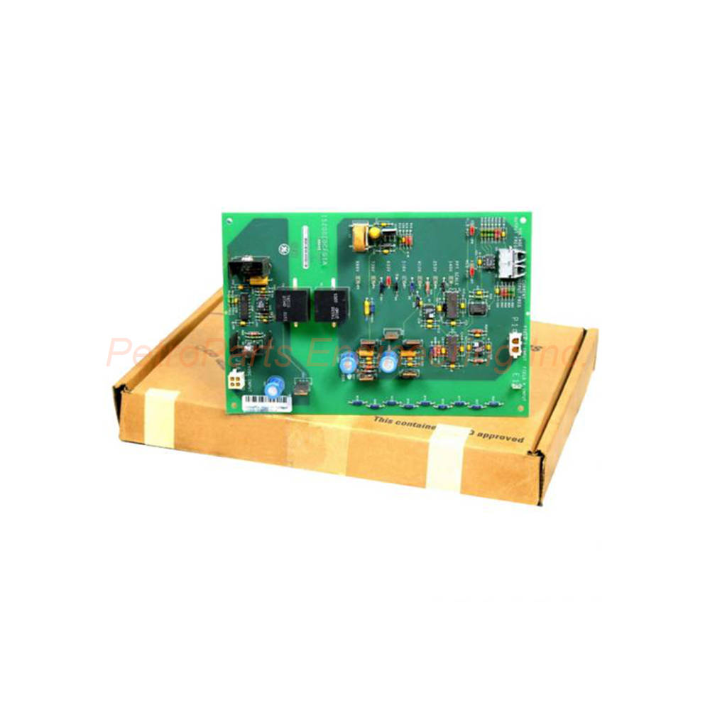
GE IS200EDCFG1A EX2100 Exciter DC Feedback Board Field Current
Introduction:
The IS200EDCFG1A is an exciter DC feedback board from General Electric. It belongs to the EX2100 series for excitation control systems. This board detects field current and voltage at the SCR bridge. It communicates with the EISB board via fiber-optic links. Consequently, it provides high noise immunity and complete voltage isolation.
![]() Customer Reviews
Customer Reviews
UBEST Automation – Trusted Global Automation Parts Supplier
We offer a wide range of in-stock industrial automation spare parts. All products come with a 12-month warranty and a 30-day refund for quality issues.
Product Attributes:
Notice: For real-time prices and inventory, please click the button below to contact us.
Product Overview: General Electric IS200EDCFG1A
The IS200EDCFG1A measures critical parameters in excitation control systems. This board monitors field current over a DC shunt at the SCR bridge. It also measures field voltage across the bridge negative terminal and shunt positive terminal. The IS200EDCFG1A sends this data to the EISB board through fiber-optic cables. Therefore, it ensures safe, noise-immune feedback for generator excitation control.
Technical Specifications
The IS200EDCFG1A operates from -30°C to +65°C ambient temperature range. It requires an external 24V DC power supply for operation. Three onboard voltage regulators generate +15V, -15V, and +5V DC outputs. The board carries a USA country of origin. Repair time is typically 3 to 7 days for this model.
Manufacturer: General Electric
Series: EX2100 Excitation Controller
Product Type: Exciter DC Feedback Board
Operating Temperature: -30°C to +65°C
External Power Supply: 24V DC
Manual Reference: GEI-100464A
The IS200EDCFG1A is an I/O terminal board input/output type. Its functional acronym is EDCF (Exciter DC Feedback). The hardware form is A and is not backward compatible. Always refer to manual GEI-100464 for detailed specifications. The general EX2100 guide GEH-6632 is also useful for system integration.
Field Voltage Feedback Circuit
The IS200EDCFG1A field voltage feedback circuit offers seven choice settings. These settings reduce the bridge voltage according to application requirements. The board monitors voltage across the bridge’s negative terminal. It also measures across the current shunt’s positive terminal. This dual measurement provides accurate field voltage data.
Field Voltage Measurement Features:
Measurement Points: Bridge negative terminal and shunt positive
Configuration Options: Seven jumper-selectable settings
Signal Processing: Differential amplifier input
Output Control: Voltage-controlled oscillator (VCO)
Scaling: Jumpered resistors for voltage scaling
Signals enter a differential amplifier on the IS200EDCFG1A for processing. After voltage scaling with jumpered resistors, the amplifier controls a VCO. The voltage-controlled oscillator converts the analog signal to frequency. This frequency travels through the fiber-optic link to the EISB board. Consequently, the control system receives accurate field voltage feedback.
Field Current Feedback Circuit
The IS200EDCFG1A measures field current at the SCR bridge over a DC shunt. This measurement produces a low-level signal with maximum 500 mV value. The low-level signal enters a differential amplifier for conditioning. The amplifier output ranges from -5V to +5V DC. This output then feeds into a voltage-controlled oscillator.
Measurement Point: DC shunt at SCR bridge
Signal Level: Maximum 500 mV low-level
Amplifier Output: -5V to +5V range
Output Control: Voltage-controlled oscillator
Isolation: Fiber-optic transmission to EISB
The IS200EDCFG1A current feedback circuit ensures precise field current monitoring. The VCO converts the amplified signal to a frequency proportional to current. This frequency travels through a dedicated fiber-optic cable. Separate fibers carry voltage and current signals to prevent crosstalk. Each signal travels on one of two fibers independently.
Fiber-Optic Communication
The IS200EDCFG1A uses fiber-optic links for noise-immune communication. Fiber optics provide high noise immunity between the EDCF and EISB boards. Complete voltage isolation is achieved through this optical connection. Two fiber types are available for different distance requirements.
Fiber-Optic Options for the IS200EDCFG1A:
Plastic Fiber: Up to 10 meters distance
Hard-Clad Silica Fiber: Up to 90 meters distance
Minimum Bend Radius: 1.5 inches for both types
Number of Fibers: One per signal (two total)
Isolation: Complete electrical isolation
For distances up to 10 meters, use plastic-type fiber with the IS200EDCFG1A. For longer runs up to 90 meters, use hard-clad silica fiber. The minimum bending radius for both fiber types is 1.5 inches. Observe this limit to prevent signal attenuation or fiber breakage. The fiber-optic link eliminates ground loop problems entirely.
Power Supply
The IS200EDCFG1A receives power from an external 24V DC source. This power enters the board through connector J16. Three onboard voltage regulators generate the required internal voltages. These regulators produce +15V DC, -15V DC, and +5V DC outputs. The +15V and -15V outputs power the analog circuits.
Input Power: 24V DC external source
Input Connector: J16
Regulated Outputs: +15V, -15V, +5V DC
PSOK LED: Green indicator for 15V outputs present
Power Monitoring: LED lights when ±15V rails are OK
The IS200EDCFG1A includes a single green LED labeled PSOK. This LED indicates that the power supply is functioning correctly. It lights when both +15V and -15V outputs are present. If this LED is off or dim, check the external 24V supply first. Then verify the onboard regulators for proper operation.
Connectors and Interfaces
The IS200EDCFG1A uses several connectors for field wiring and communication. Connector J16 receives the 24V DC power supply input. Connector P1 connects to the field current shunt resistance voltage. The field voltage input uses a stab-on connector labeled E1. Fiber-optic ports handle current and voltage feedback to the control system.
Connector Summary for the IS200EDCFG1A:
J16: 24V DC power input
P1: Field current shunt voltage input
E1: Stab-on connector for field voltage input
Fiber Port 1: Current feedback output
Fiber Port 2: Voltage feedback output
When installing the IS200EDCFG1A, connect the fiber-optic cables carefully. Clean all fiber ends before insertion into the transceivers. Route fibers away from sharp edges and hot surfaces. Secure fibers with gentle cable ties to prevent movement. Test the communication link before commissioning the excitation system.
Jumper Settings and Configuration
The IS200EDCFG1A uses jumpered resistors for field voltage scaling. Seven choice settings are available for different bridge applications. These settings reduce the bridge voltage appropriately for measurement. The correct setting depends on the nominal field voltage of the generator. Consult manual GEI-100464 for specific jumper positions.
Application: SCR bridge voltage reduction
Number of Settings: Seven selectable options
Adjustment Method: Physical jumper placement
Purpose: Scale voltage to VCO input range
Documentation: Manual GEI-100464
Always configure the IS200EDCFG1A jumpers before installing the board. Incorrect settings may cause inaccurate feedback or damage. Record the jumper positions for future maintenance reference. When replacing a failed board, duplicate the original jumper settings exactly.
Board Layout and Indicators
The IS200EDCFG1A has a clear board layout as shown in Figure 2. One green PSOK LED shows power supply status prominently. Connectors are positioned for easy access during installation. Fiber-optic transceivers are located near the board edge. The layout supports easy troubleshooting and replacement.
LED Indicators: PSOK (green) for ±15V power OK
Connector Layout: J16, P1, and E1 clearly labeled
Fiber Ports: Two ports for current and voltage
Jumpers: Accessible for configuration changes
Form Factor: Hardware Form A
The IS200EDCFG1A hardware is not backward compatible with previous versions. Always verify the form factor when ordering replacements. Form A boards require matching firmware and system configuration. Consult GE technical support if compatibility questions arise.
Installation Guidelines
Install the IS200EDCFG1A in the designated EX2100 rack slot. Apply 24V DC power to connector J16 from an external supply. Connect the field current shunt wires to connector P1. Attach the field voltage wires to the stab-on E1 terminal. Finally, connect the fiber-optic cables to the EISB board.
Key Installation Points for the IS200EDCFG1A:
Power Supply: External 24V DC regulated source
Fiber Handling: Minimum bend radius 1.5 inches
Cleaning: Use fiber cleaning kit before connection
Jumper Setting: Configure before installation
Grounding: Ensure proper system ground reference
Never connect or disconnect fiber cables with power applied. Always use approved fiber cleaning tools for the IS200EDCFG1A. Keep fiber ends covered when not connected immediately. Test the fiber link with a visible light source if available. Replace any damaged fiber cables before system startup.
Package Contents
Your purchase of the IS200EDCFG1A includes:
(1) GE Exciter DC Feedback Board – IS200EDCFG1A
(1) Anti-static protective packaging
(1) Quick reference installation note
Frequently Asked Questions (FAQ)
Q: What is the functional purpose of the IS200EDCFG1A?
A: The IS200EDCFG1A measures field current and voltage at the SCR bridge. It sends this feedback to the EISB control board via fiber optics.
Q: What fiber-optic cable works with the IS200EDCFG1A?
A: The IS200EDCFG1A uses plastic fiber for distances up to 10 meters. For up to 90 meters, use hard-clad silica fiber cable instead.
Q: What does the PSOK LED indicate on the IS200EDCFG1A?
A: The green PSOK LED on the IS200EDCFG1A shows that ±15V power is present. If off, check the external 24V supply and onboard regulators.
Q: What is the operating temperature range for the IS200EDCFG1A?
A: The IS200EDCFG1A operates reliably from -30°C to +65°C. This suits most industrial excitation control room environments.
Q: Is the IS200EDCFG1A backward compatible with older versions?
A: No, the IS200EDCFG1A is hardware Form A and not backward compatible. Always verify form factor when replacing boards.