
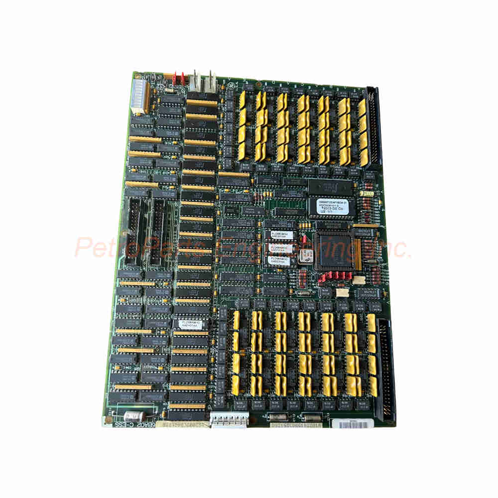
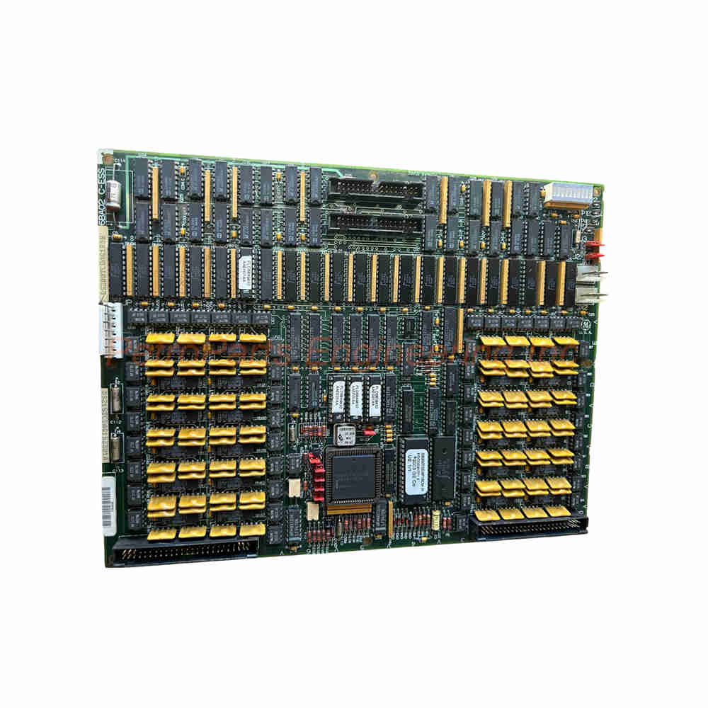
GE DS200TCDAG1BDB Mark V Digital I/O Board TCDA 12 Relays
Introduction:
The DS200TCDAG1BDB is a digital I/O board from General Electric. It belongs to the Mark V Speedtronic series for turbine control systems. This board manages contact input signals and relay output signals. It communicates via IONET with other Mark V components. Consequently, it is essential for steam and gas turbine automation.
 Customer Reviews
UBEST Automation – Trusted Global Automation Parts Supplier
We offer a wide range of in-stock industrial automation spare parts. All products come with a 12-month warranty and a 30-day refund for quality issues.
Product Attributes:
Notice: For real-time prices and inventory, please click the button below to contact us.
Product Overview: General Electric DS200TCDAG1BDB
The DS200TCDAG1BDB serves as an interface for contact inputs and relay outputs. Software configuration customizes these I/O functions for specific applications. This board operates within the Mark V <R1> core environment. It is not the original TCDA board but includes three significant revisions. Therefore, it offers improved functionality over the parent DS200TCDAG1 version.
Technical Specifications
The DS200TCDAG1BDB requires +5V DC at 6A for proper operation. It provides 12 relay channels for contact output control. Power supply voltage for these relays is 28V DC. The board uses surface mount technology for compact construction. Operating temperature ranges from -30°C to +65°C for industrial use.
-
Part Number: DS200TCDAG1BDB
-
Manufacturer: General Electric
-
Series: Mark V Speedtronic
-
Functional Abbreviation: TCDA
-
Assembly Type: Normal Assembly
-
Revision Quantity: 3 revisions total
The DS200TCDAG1BDB measures 15.9 cm high by 17.8 cm wide. Mounting is accomplished via DIN-rail for easy installation. The country of origin is the United States of America. Repair time is typically 3 to 7 days for this model. Manual GEI-100182B provides detailed technical information.
Backward Compatibility
The DS200TCDAG1BDB maintains backward compatibility with earlier revisions. Specifically, it works with the first two revisions of the TCDA board. This allows replacement of older boards without system changes. However, verify your system configuration before installing this board. Always consult the manual for revision-specific details.
-
Parent Board: DS200TCDAG1 (original version)
-
Backward Compatibility: First two revisions supported
-
Revision Count: Three total for this BDB version
-
Application: Direct replacement for earlier TCDA boards
-
Verification: Check system manual before installation
The DS200TCDAG1BDB includes improvements over the original design. These enhancements address reliability and performance issues. The three revisions incorporate field experience feedback. Consequently, this board is more robust than earlier versions.
Hardware Configuration Jumpers
The DS200TCDAG1BDB features eight hardware jumpers (J1 through J8). J1 and J8 are reserved for factory testing purposes only. J2 and J3 control IONET termination resistors for network configuration. J4 through J6 configure the board’s IONET ID address.
Jumper Functions on the DS200TCDAG1BDB:
-
J1: Factory testing (do not modify)
-
J2: IONET termination resistor
-
J3: IONET termination resistor
-
J4: IONET ID addressing
-
J5: IONET ID addressing
-
J6: IONET ID addressing
-
J7: Enables stall timer function
-
J8: Test enable (factory use only)
The DS200TCDAG1BDB J4 through J6 jumpers should remain at factory settings. Changing these IONET ID jumpers disrupts system communication. J7 enables the stall timer when closed appropriately. J8 is for test enable and should not be adjusted. For detailed settings, consult Appendix A in the manual.
Signal Management
The DS200TCDAG1BDB manages digital contact input signals from DTBA and DTBB terminal boards. It also handles contact output signals (relay/solenoid) from TCRA boards. These signals are relayed via IONET to other system components. The TCQC board receives signals in R1 and R5 cores. Alternatively, the CTBA terminal board receives signals when R3 is included.
Signal Flow for the DS200TCDAG1BDB:
-
Input Source A: DTBA terminal board (contact inputs)
-
Input Source B: DTBB terminal board (contact inputs)
-
Output Destination A: TCRA boards (relay/solenoid)
-
Network: IONET communication protocol
-
Receiving Boards: TCQC (R1/R5) or CTBA (R3)
The DS200TCDAG1BDB works within the Mark V’s R1 core primarily. Other boards like TCEA, TCQE, TCQA, UCPB, and STCA also reside in this core. All these boards work together for complete turbine control. Replacement of any core board may require checking compatibility.
Connector Description
The DS200TCDAG1BDB incorporates multiple connectors for system integration. Each connector serves a specific signal routing purpose. Proper connection of all ports is essential for board function. The following table summarizes each connector’s role.
Connector Summary for the DS200TCDAG1BDB:
-
JP: Distributes power from TCPS board to Q11, Q21, Q51 cores
-
JQ: Connects to DTBA board for contact input signals
-
JR: Connects to DTBB board for contact input signals
-
JO1: Transmits output signals to TCRA in location four
-
JO2: Transmits output signals to TCRA in location five
-
JX1: Shielded twisted pair for IONET signals
-
JX2: Alternate IONET signal connection
The DS200TCDAG1BDB JP connector receives power from the TCPS board. This power distributes to multiple cores in the system. JQ and JR connectors bring contact input signals from terminal boards. JO1 and JO2 send relay output signals to TCRA boards. Either JX1 or JX2 can be used for IONET communication.
Software Configuration
The DS200TCDAG1BDB uses the I/O Configuration Editor on the HMI for setup. This software configures contact input inversions for each channel. Constants are entered through the operator interface. Software configuration complements the hardware jumper settings. Always save configurations before making hardware changes.
-
Configuration Tool: I/O Configuration Editor on HMI
-
Adjustable Parameters: Contact input inversions
-
Hardware Interface: Operator interface screen
-
Complementary To: Jumper hardware settings
-
Documentation: Refer to manual for procedure
The DS200TCDAG1BDB software settings persist through power cycles. Verify all settings after replacing a failed board. Backup configurations before performing any maintenance. This ensures quick restoration if settings are lost.
Internal Components
The DS200TCDAG1BDB incorporates many hardware components for voltage limiting. An LED panel provides visual status indication for diagnostics. Resistor network arrays manage signal levels appropriately. Pin connectors and integrated circuits handle signal processing.
Hardware Components on the DS200TCDAG1BDB:
-
LED Panel: Visual status indicators
-
Resistor Networks: Signal level management
-
Pin Connectors: Board-to-cable interfaces
-
Integrated Circuits: Signal processing logic
-
Capacitors: Voltage filtering and smoothing
-
Relays: 12 channel output switching
-
Vertical Pin Plugs: Stacking connections
Most components on the DS200TCDAG1BDB serve voltage limiting or reduction. This protects downstream circuits from overvoltage conditions. The board receives daily wear protection from conformal coating. This coating insulates components from moisture and dust. Consequently, reliability in harsh environments is improved significantly.
Physical Characteristics
The DS200TCDAG1BDB is factory-drilled for flexible mounting options. Alignment markings along the board edge aid installation. The normal assembly type indicates standard construction (not special). Conformal coating protects the base board from environmental stress. All components are surface-mounted for compact density.
-
Mounting: DIN-rail compatible
-
Coating: Normal style conformal coating
-
Drilling: Factory-drilled mounting holes
-
Markings: Edge markings for alignment
-
Assembly Type: Normal (not heavy duty)
Handle the DS200TCDAG1BDB with ESD precautions at all times. The conformal coating does not eliminate ESD sensitivity. Store the board in its anti-static bag until installation. Inspect for damaged components before mounting. Any visible damage suggests the board requires repair.
Installation Guidelines
Install the DS200TCDAG1BDB in the designated Mark V rack location. Ensure all power is removed before handling the board. Mount the board on DIN rail or using panel screws. Connect all required cables to the appropriate connectors. Verify jumper settings before applying system power.
Key Installation Points for the DS200TCDAG1BDB:
-
Power: De-energize system before installation
-
ESD Protection: Use grounded wrist strap
-
Jumper Check: Verify J4-J6 at factory settings
-
Cable Routing: Keep IONET cables away from power
-
LED Check: Verify status after power-up
After installing the DS200TCDAG1BDB, apply +5V DC power to the system. Observe the LED panel for proper initialization. Then verify communication with the TCQC board via IONET. Finally, test contact inputs and relay outputs under software control. Any fault indicated requires troubleshooting per manual GEI-100182B.
Package Contents
Your purchase of the DS200TCDAG1BDB includes:
-
(1) GE Digital I/O Board – DS200TCDAG1BDB
-
(1) Anti-static protective packaging
-
(1) Quick reference installation card
Frequently Asked Questions (FAQ)
Q: What is the primary function of the DS200TCDAG1BDB?
A: The DS200TCDAG1BDB manages digital contact inputs and relay outputs. It interfaces between terminal boards and the Mark V control system via IONET.
Q: How many relay channels does the DS200TCDAG1BDB provide?
A: The DS200TCDAG1BDB provides 12 relay channels for contact output control. Each channel switches 28V DC loads as configured by software.
Q: Is the DS200TCDAG1BDB backward compatible with older TCDA boards?
A: Yes, the DS200TCDAG1BDB works with the first two revisions of TCDA boards. This allows direct replacement without system modification.
Q: What power supply does the DS200TCDAG1BDB require?
A: The DS200TCDAG1BDB requires +5V DC at 6A. The relay power supply voltage is 28V DC separately.
Q: What is the operating temperature range for the DS200TCDAG1BDB?
A: The DS200TCDAG1BDB operates from -30°C to +65°C reliably. This suits typical turbine control room environments.