
Allen-Bradley 1746-NI4 | SLC 500 Analog Input Module 4 Channel 16-Bit
Introduction:
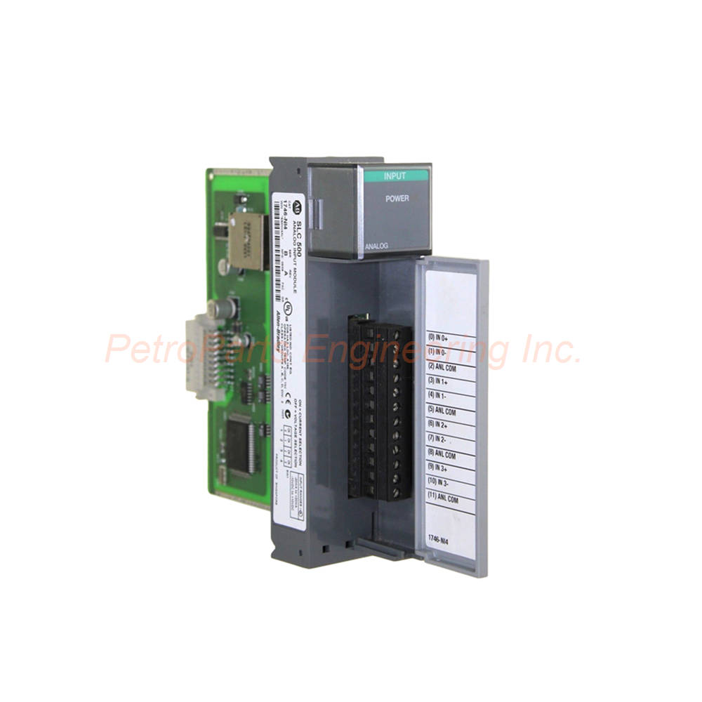
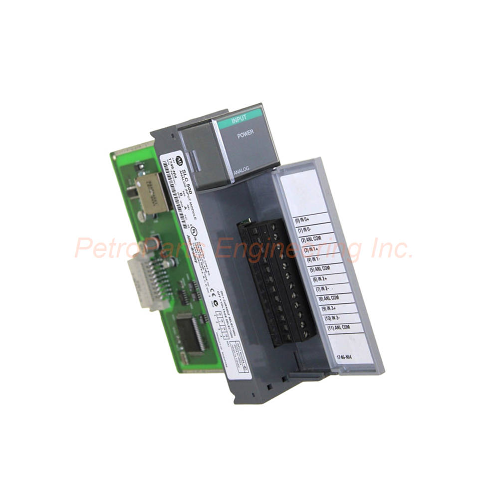
Allen-Bradley 1746-NI4 SLC 500 Analog Input Module. 4 differential channels with 16-bit resolution. Voltage or current selectable.
 Customer Reviews
UBEST Automation – Trusted Global Automation Parts Supplier
We offer a wide range of in-stock industrial automation spare parts. All products come with a 12-month warranty and a 30-day refund for quality issues.
Product Attributes:
Notice: For real-time prices and inventory, please click the button below to contact us.
Product Overview
The Allen-Bradley 1746-NI4 is an analog input module for the SLC 500 system. This module provides four non-isolated differential input channels. Each channel is individually selectable for voltage or current input. The Allen-Bradley 1746-NI4 occupies a single slot in the SLC 500 chassis. Users trust this module for precise analog measurement in monitoring and control applications.
Technical Specifications
The 1746-NI4 delivers accurate analog conversion with flexible input configuration. Below are the complete technical details.
General Specifications
Manufacturer: Rockwell Automation for industrial control reliability.
Brand: Allen-Bradley for SLC 500 compatibility.
Part Number: 1746-NI4 for precise identification.
Series: SLC 500 programmable controller family.
Module Type: Analog I/O Module (4-channel analog input).
UPC: 10662073735905 for universal product identification.
UNSPSC: 32151705 for classification.
Chassis Location: Any I/O module slot except slot 0.
Compatibility: Fixed or modular style hardware.
Input Channel Specifications
Number of Channels: Four (4) non-isolated differential inputs.
Input Signal Category: -20 to +20 mA or -10 to +10V DC.
Channel Configuration: User-selectable per channel via DIP switch.
Input Type: Differential for noise rejection.
Removable Terminal Block: Provides connections for each analog input.
Conversion Specifications
Conversion Type: Delta-Sigma Modulation.
Converter Resolution: 16 bit.
Current Input Coding: -16,384 to +16,384.
Voltage Input Coding: -32,768 to +32,767.
Resolution (Current): 1.22070 µA per LSB.
Resolution (Voltage): 305.176 µV per LSB.
Update Time: 512 microseconds.
Step Response: 60 milliseconds.
Bandwidth: 10 Hertz.
Repeatability: ±1 LSB.
Non-linearity: 0.01%.
Current Input Specifications
Input Range (Nominal): ±20 mA.
Input Range (Maximum): ±30 mA.
Input Impedance: 250 Ohms.
Gain Error Drift: ±67 ppm/°C.
Overall Accuracy at 25°C: ±0.365% of full scale.
Overall Accuracy at 60°C: ±0.642% of full scale.
Accuracy Drift: +79 ppm/°C of full scale.
Voltage Input Specifications
Input Range: ±10 Volts DC -1 LSB.
Input Impedance: 1 mega Ohm.
Gain Error Drift: ±57 ppm/°C.
Accuracy Drift: +63 ppm/°C of full scale.
Overall Accuracy at 25°C: ±0.284% of full scale.
Overall Accuracy at 60°C: ±0.504% of full scale.
Backplane Current Specifications
Backplane Current (5 Volts): 25 milliamps (35 mA max listed).
Backplane Current (24 Volts DC): 85 milliamps.
Power Draw: Moderate for four-channel analog input.
Physical and Connection Specifications
Cable Lengths: 0.5, 1, 2.5, or 5.0 meters standard.
AIFM Connector: 15-pin D-shell.
DIP Switches: On circuit board for input voltage or current selection.
LED Indicators: Built-in for channel status and module operation.
Diagnostic Interrupt: Controller's diagnostic interrupt for status access.
Important Usage Caution
Do not connect voltage source to channel configured for current input.
Incorrect configuration may cause module damage.
Always verify DIP switch settings before applying signals.
Installation Guide
Follow these steps to install the Allen-Bradley 1746-NI4 correctly.
Power Down the Chassis: Turn off all power to the SLC 500 rack.
Locate an Available Slot: Find any I/O slot except slot 0.
Set DIP Switches: Configure each channel for voltage or current input.
Insert the Module: Slide the 1746-NI4 into the slot carefully.
Secure the Module: Lock using the retaining clips at top and bottom.
Wire Removable Terminal Block: Connect analog signals to the RTB.
Use Differential Wiring: Connect each channel as differential input.
Select Cable Length: Choose 0.5, 1, 2.5, or 5.0 meter cable.
Connect 15-Pin D-shell: Attach the AIFM connector if used.
Apply Power: Turn on the backplane power to the chassis.
Check LED Indicators: Verify status LEDs for proper operation.
Configure Scaling: Use scaling algorithm to display process variables.
Test Each Channel: Apply known signals and verify readings.
Monitor Accuracy: Check overall accuracy at ambient temperature.
Installation Notes
Never connect voltage to a channel configured for current input.
The module cannot go in slot 0 of the SLC 500 chassis.
Delta-Sigma conversion provides 16-bit resolution.
Update time is 512 microseconds per channel.
LED indicators provide quick module diagnostics.
Packaging List
This unit ships as a new and original product.
Allen-Bradley 1746-NI4 Analog I/O Module
Removable terminal block (RTB)
Product data sheet with DIP switch settings
Anti-static factory packaging bag
Frequently Asked Questions (FAQ)
1. How many analog input channels does the 1746-NI4 provide?
The Allen-Bradley 1746-NI4 provides four non-isolated differential input channels. Each channel is individually selectable for voltage or current.
2. What input signal ranges does this module support?
The 1746-NI4 supports -20 to +20 mA for current input. For voltage input, it supports -10 to +10V DC.
3. What is the resolution of the 1746-NI4 analog module?
The Allen-Bradley 1746-NI4 has 16-bit resolution. Current input coding ranges from -16,384 to +16,384. Voltage input coding ranges from -32,768 to +32,767.
4. Can I install the 1746-NI4 in slot 0 of the SLC 500 chassis?
No, the 1746-NI4 cannot be installed in slot 0. It works in any other I/O module slot of the SLC 500 chassis.
5. What happens if I connect voltage to a current-configured channel?
Connecting voltage to a channel configured for current input may cause incorrect module operation or module damage. Always verify DIP switch settings before wiring.
Welcome to learn about our business. We are a leading global provider of automation equipment and will provide you with complete and cost-effective product solutions. You are welcome to choose us, and our services will make you a long-term partner like our other customers.
Now please let us know your needs and suggestions.
About Ubest
Ubest Automation is a leading global provider of automation products, with deep partnerships with major automation manufacturers to provide customers with customized business solutions, cost-effective products, and comprehensive services.
Product Center
Contact Us
Phone:+86 180 3000 5825
Address:Room 7A, No. 59 Hubin North Road, Siming District Xiamen City China
Email: [email protected]
Contact: Klaus
Industry Links
© 2026, Ubest Automation Limited All Rights Reserved. sitemap