
Allen-Bradley 1746-IV8 SLC 500 Input Module 8 Channel 24VDC Source
Introduction:
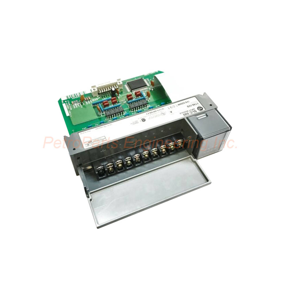
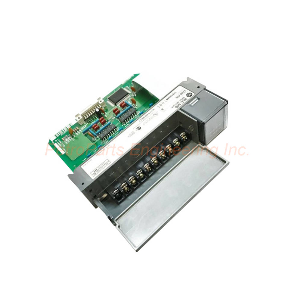
The 1746-IV8 is a discrete input module for Allen-Bradley SLC 500 systems. It provides 8 sourcing input channels rated at 24VDC. This single-slot module draws only 50mA from the backplane.
 Customer Reviews
UBEST Automation – Trusted Global Automation Parts Supplier
We offer a wide range of in-stock industrial automation spare parts. All products come with a 12-month warranty and a 30-day refund for quality issues.
Product Attributes:
Notice: For real-time prices and inventory, please click the button below to contact us.
Product Overview
The 1746-IV8 belongs to the SLC 500 Series. Its product type is a Discrete Input Module. The product classification is I/O Modules. The current price for this item is ¥1,850 RMB, and the product gross weight is 0.28 kg.
Rockwell Automation designed this module under the Allen-Bradley brand for SLC 500 PLC systems. The 1746-IV8 features eight (8) 24 Volt DC sourcing input channels arranged in a single group . This module directly interfaces with field devices such as limit switches, auxiliary contacts, and sensors. Therefore, the SLC 500 control system recognizes state changes for user program execution.
Technical Specifications
Input Channels and Configuration
The module provides 8 input channels organized as one group . The input type is sourcing , meaning the module expects positive voltage from the field device. Typical compatible devices include limit switches, auxiliary contacts, proximity sensors, and push buttons. Each channel monitors the presence or absence of DC voltage.
Voltage Ratings
The nominal input voltage is 24 VDC . The acceptable input voltage range spans 10 to 30 VDC , accommodating typical industrial power variations. The off-state voltage maximum is 5.0 VDC . When the input is OFF, the module ignores signals below this threshold. Therefore, noise immunity improves significantly.
Current Specifications
The nominal input current is 8 mA at 24 VDC . The off-state current maximum is 1 mA . This low off-state current prevents false triggering from leakage currents. Consequently, the 1746-IV8 works reliably with solid-state sensors and long cable runs.
Signal Delay
The maximum ON signal delay measures 8 milliseconds . Similarly, the maximum OFF signal delay also measures 8 milliseconds . These symmetrical delays simplify timing calculations in control programs. For high-speed applications, consider these delays when designing your logic.
Backplane Current
The backplane current consumption at 5 VDC is 50 mA (0.050 Amperes) . At 24 VDC , the module draws 0 mA from the backplane. This low power draw minimizes load on the system power supply. Multiple 1746-IV8 modules can operate together without exceeding power budget limits.
Temperature and Humidity
The operating temperature range spans 0 to +60°C (+32 to +140°F) . The storage temperature range extends from -40°C to +85°C (-40°F to +185°F) . Relative humidity tolerance reaches 5 to 95% without condensation . Therefore, this module suits a wide range of industrial environments.
Physical Installation
The 1746-IV8 occupies one slot in any SLC 500 chassis. The module can install in any vacant slot. No external power supply is needed, as the module draws power from the backplane. LED indicators on the front panel show the status of each input channel.
Wiring Requirements
Signal termination requires 14 AWG (2 mm²) cables. For proper installation, use appropriate wire gauges for your field devices. Follow standard SLC 500 wiring practices for reliable connections.
Important Safety Notes
The 1746-IV8 is supplied as open type equipment intended for industrial environments. Stop power before removing this module . Removing or inserting the module with power applied can cause an electrical arc. Arcing can cause personal injury and excessive wear to contacts. Worn contacts may create electrical resistance, leading to reduced product reliability.
Installation Guide
Follow these steps to install your 1746-IV8 correctly.
Power Down the Chassis: Disconnect power from the SLC 500 chassis power supply. This prevents electrical arcing and personal injury.
Select a Slot: Choose an available slot in the SLC 500 chassis. The 1746-IV8 occupies one slot only.
Insert the Module: Align the 1746-IV8 with the slot guides. Push firmly until the module seats into the backplane connector.
Secure the Module: Tighten the retaining screws at the top and bottom. This secures the input module in place.
Connect Field Devices: Wire your sourcing field devices to the input terminals. Use 14 AWG (2 mm²) cables for signal termination.
Verify Voltage Range: Ensure each input signal falls within 10-30 VDC . The nominal voltage is 24 VDC.
Apply Power: Restore power to the SLC 500 chassis. Verify the module powers up without errors.
Monitor Input Status: Check the front panel LED indicators. Each LED lights when the corresponding input channel is active.
Test Operation: Activate each field device individually. Confirm that the 1746-IV8 detects each state change correctly.
Package List
1 x 1746-IV8 Discrete Input Module (8 channel, 24VDC sourcing)
1 x Terminal label set
2 x Module retaining screws (pre-installed)
1 x Installation instruction manual
Note: Field wiring and termination accessories are sold separately.
Frequently Asked Questions (FAQ)
1. What is the difference between sourcing and sinking inputs?
Sourcing inputs expect positive voltage from the field device to activate. The 1746-IV8 uses sourcing inputs, so the field device supplies +24VDC to the input channel. For sinking inputs, the module supplies the voltage and the field device switches to ground.
2. What is the maximum signal delay for this module?
Both ON and OFF transitions have a maximum delay of 8 milliseconds . This symmetrical delay simplifies control programming. For faster response, consider the 1746-IB8 module which offers 1ms delays.
3. Can I use this module with 12VDC field devices?
Yes, the 1746-IV8 accepts input voltages from 10 to 30 VDC . Therefore, 12VDC signals work within this range. However, the nominal input current of 8mA assumes 24VDC. At lower voltages, the input current will decrease proportionally.
4. Why must I remove power before installing or removing the module?
Removing or inserting the module with power applied can cause an electrical arc . Arcing can cause personal injury and excessive wear to contacts. Worn contacts may create electrical resistance, reducing product reliability. Always power down the chassis first.
5. How many 1746-IV8 modules can I install in one system?
The number is limited by three factors: the host processor's I/O capacity, the number of available chassis slots, and the backplane power budget. Each module draws 50 mA at 5 VDC , so calculate total power consumption across all modules.
Welcome to learn about our business. We are a leading global provider of automation equipment and will provide you with complete and cost-effective product solutions. You are welcome to choose us, and our services will make you a long-term partner like our other customers.
Now please let us know your needs and suggestions.
About Ubest
Ubest Automation is a leading global provider of automation products, with deep partnerships with major automation manufacturers to provide customers with customized business solutions, cost-effective products, and comprehensive services.
Product Center
Contact Us
Phone:+86 180 3000 5825
Address:Room 7A, No. 59 Hubin North Road, Siming District Xiamen City China
Email: [email protected]
Contact: Klaus
Industry Links
© 2026, Ubest Automation Limited All Rights Reserved. sitemap