
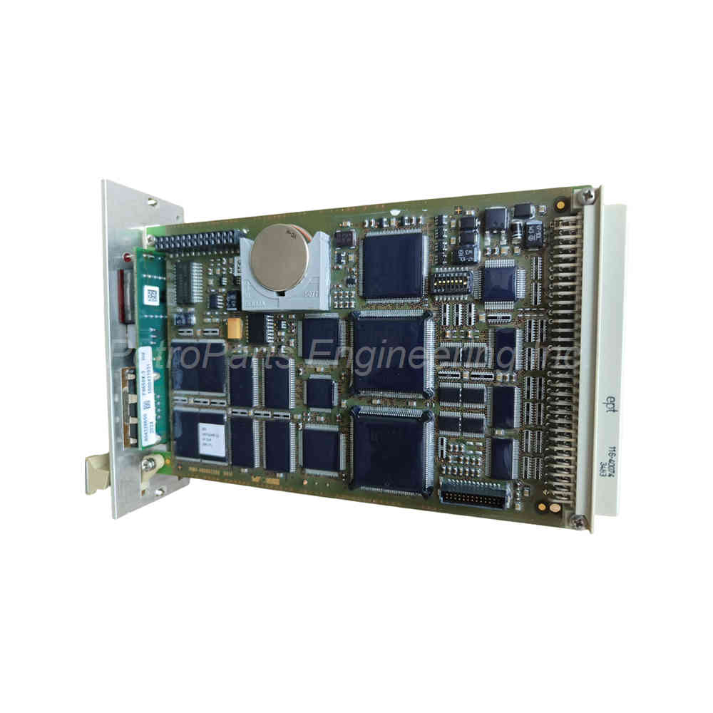
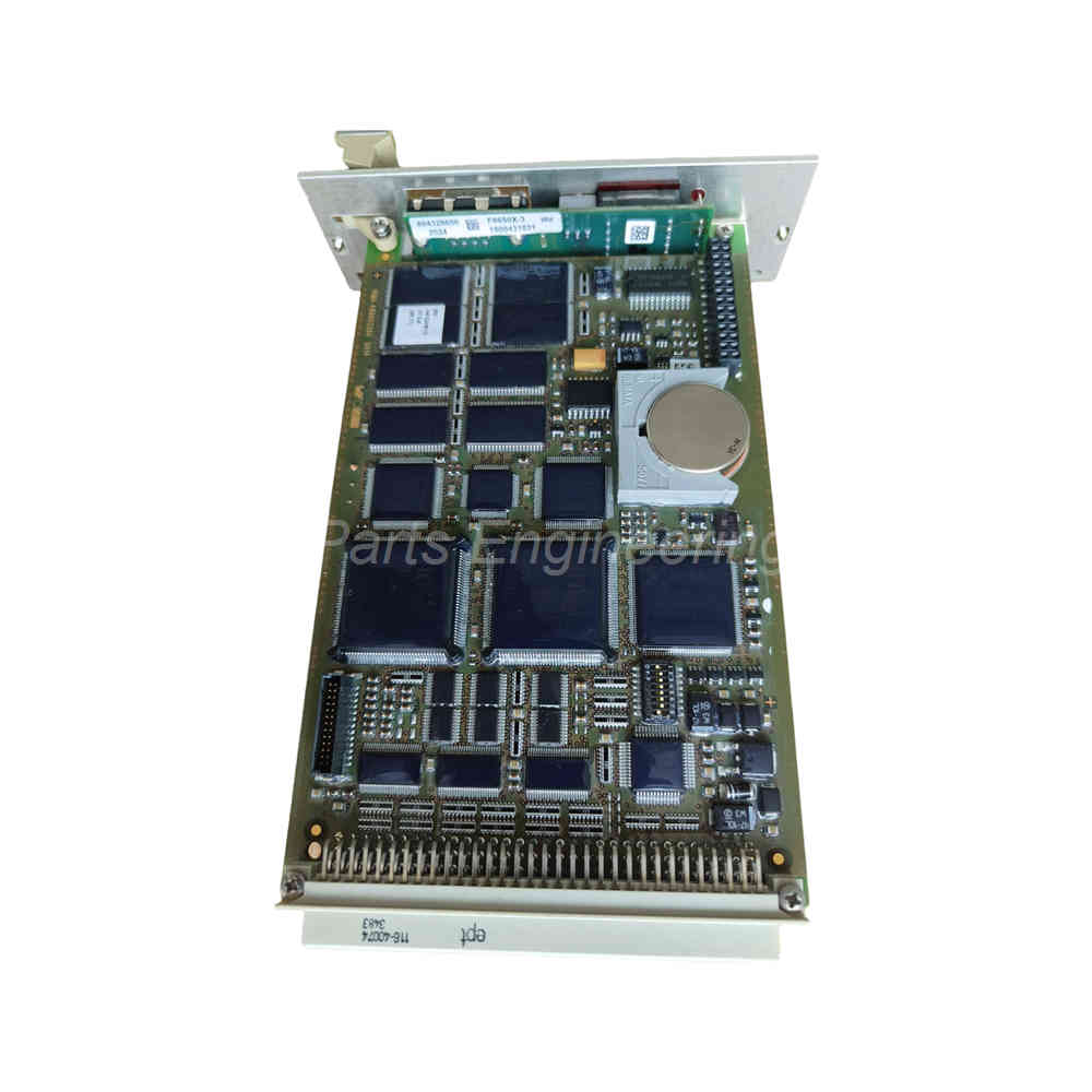
HIMA F 8650X Central Module SIL3 PES H51q Safety Controller CPU
Introduction:
HIMA F 8650X central module for PES H51q systems. SIL 3 safety-rated, 25MHz 32-bit CPU, RS485 interfaces, diagnostic display. New original.
 Customer Reviews
UBEST Automation – Trusted Global Automation Parts Supplier
We offer a wide range of in-stock industrial automation spare parts. All products come with a 12-month warranty and a 30-day refund for quality issues.
Product Attributes:
Notice: For real-time prices and inventory, please click the button below to contact us.
HIMA F8650X Central Module for PES H51q Safety Systems
Product Overview and Core Function
The HIMA F8650X serves as a central module for the PES H51q-MS, -HS, and -HRS systems. As a result, it provides safety-related control for critical industrial processes. Specifically, this module is applicable up to SIL 3 according to IEC 61508. Consequently, the HIMA F8650X meets the highest safety integrity requirements for emergency shutdown and burner management.
Key Technical Parameters and Processor Architecture
The HIMA F8650X features two INTEL 386EX microprocessors operating at 32 bits. For instance, the clock frequency runs at 25 MHz for both CPUs. Each microprocessor contains 1 MB of Operating System Flash-EPROM. Similarly, each CPU includes 1 MB of User Program Flash-EPROM. In addition, each microprocessor has 1 MB of Data SRAM memory. Therefore, the degree of utilization depends on the operating system version.
Power Requirements and Operating Data
The HIMA F8650X requires internal operating power at 5 V / 2 A from the backplane. The module draws this power through the PES H51q rack. Consequently, ensure your power supply module can handle this load. No external 24 VDC connection is needed directly on this central module.
Safety Features and Watchdog Function
This module includes a safety-related watchdog for fault monitoring. For example, the watchdog provides a 24 V output rated for up to 500 mA. This output is short-circuit proof for reliable operation. Shutdown on fault occurs automatically when the watchdog triggers. As a result, the HIMA F8650X ensures safe system behavior during critical failures.
RS 485 Interfaces and Pinout Details
The HIMA F8650X offers two serial interfaces for communication. Specifically, both interfaces use RS 485 protocol with electric isolation. The 9-pin connector follows this assignment:
Pin RS 485 Signal Meaning
1 – – not used
2 – RP 5 V decoupled by diodes
3 A/A’ RxD/TxD-A Receive/Transmit Data A
4 – CNTR-A Control signal A
5 C/C’ DGND Data Ground
6 – VP 5 V positive pole of power supply
7 – – not used
8 B/B’ RxD/TxD-B Receive/Transmit Data B
9 – CNTR-B Control signal B
Therefore, these isolated ports resist ground loops and electrical noise effectively.
Ethernet Communication via F8627X Module
The HIMA F8650X connects to Ethernet networks through the F8627X communication module. For instance, it supports connection of the central module to a PADT using ELOP II TCP. Similarly, it connects to other communication partners within an Ethernet network. Specifically, the system supports safeethernet and Modbus TCP protocols. The communication runs from the central module via the backplane bus to the F8627X. Consequently, data flows from the Ethernet ports of the F8627X into the Ethernet network and vice versa.
Special Features and Software Support
The HIMA F8650X includes self-education functionality. For example, this feature works from operating system BS41q/51q V7.0-8 (05.31). Similarly, ELOP II TCP is supported from the same operating system version. Further information about bus station numbers and ELOP II TCP is available in the F8627X data sheet. Therefore, refer to the operating system manual of H41q/H51q and the safety manual for complete details.
Diagnostic Display and Error Indication
The central module features a four-digit alphanumerical display. In addition, two LEDs show general error information. Specifically, the CPU LED indicates errors for the central module. The IO LED shows errors for testable input/output modules. Two toggle switches request detailed error information. A push-button ACK resets the error indication. In failure stop mode, ACK behaves like restarting the system. Therefore, refer to the documentation “Functions of the operational system BS 41q/51q” for error code lists.
Start-up and Maintenance Notes
The buffer battery has a specified lifetime without voltage feeding. For instance, at TA = 25 °C, the battery lasts 1000 days. At TA = 60 °C, the battery lasts 200 days. Therefore, replace the buffer battery after 6 years at the latest. Alternatively, replace it within three months when the BATI display appears. The lithium battery type is CR 2477N (HIMA part no. 44 0000018). You can change the battery while the CPU remains in operation.
Check the bus station number and transmission rate at switch S1 for correct settings. Specifically, verify these settings during initial installation. When upgrading an F 8650 to an F8650X module, the fan concept must also be changed. Consequently, follow the upgrade instructions carefully.
Mechanical Construction and Space Requirements
The HIMA F8650X uses two European standard PCBs for the core electronics. A separate PCB handles the diagnostic display functions. The space requirement is 8 SU (standard units) in a 19-inch rack. Consequently, plan your cabinet layout accordingly. The robust construction ensures reliable operation in industrial environments.
Installation Guide
Mount the HIMA F8650X in a suitable PES H51q rack with 8 SU space. First, verify the fan concept meets requirements for F8650X upgrades. Set the correct bus station number and transmission rate on switch S1. Then, connect the RS 485 interfaces using the pinout table above. For Ethernet communication, install an F8627X module in the same rack. Finally, verify the diagnostic display shows normal operation after power-up.
Complete Package Contents
HIMA F8650X Central Module (1 unit)
Two INTEL 386EX 32-bit microprocessors (pre-installed)
Operating system Flash-EPROM (1 MB per CPU)
User program Flash-EPROM (1 MB per CPU)
Data SRAM (1 MB per CPU)
Two RS 485 serial interfaces with electric isolation
Four-digit alphanumerical diagnostic display
Two error LEDs (CPU and IO)
Two toggle switches for error details
Push-button ACK for error reset
Safety watchdog with 24 V / 500 mA output
Two European standard PCBs
One diagnostic display PCB
Buffer battery (CR 2477N type)
Frequently Asked Questions (FAQ)
1. What safety level does the HIMA F8650X support?
The HIMA F8650X is applicable up to SIL 3 according to IEC 61508. Therefore, it suits high-risk industrial applications.
2. What processors are used in this central module?
The module uses two INTEL 386EX 32-bit microprocessors. Consequently, they run in clock-synchronized mode at 25 MHz for safety.
3. How do I connect the F8650X to an Ethernet network?
Connect through the F8627X communication module via the backplane bus. Specifically, this supports safeethernet and Modbus TCP protocols.
4. What is the buffer battery lifetime for the HIMA F8650X?
The battery lasts 1000 days at 25°C and 200 days at 60°C. Replace the battery after 6 years or within three months of BATI display.
5. What must I change when upgrading from F8650 to F8650X?
When upgrading from an F8650 to an F8650X module, the fan concept must also be changed. Consequently, follow the upgrade documentation carefully.